


103904-UIM-B-0505
Unitary Products Group
5
INDOOR UNIT PREPARATION
Prepare Air Handler for installation as follows:
1.
Attach coil casing to blower section in a way appropriate to indoor
unit application. See appropriate “BLOWER / COIL ASSEMBLY”
instructions for G2FD Coils.
2.
Confirm the metering device.
NOTE: If a humidistat accessory is installed with the system, a thermal
expansion valve kit must be installed on the indoor side.
NOTE: Instructions for installing accessories are included with the
accessories.
3.
Attach Filter Rack Accessory if applicable. The filter rack is
designed for use with G2FD coil or blower section in a downflow
configuration.
4.
For upflow and horizontal applications, insert filter in the filter com-
partment below the coil.
BLOWER / COIL ASSEMBLY UPFLOW AND
HORIZONTAL INSTALLATIONS
NOTE: See coil instructions prior to assembly for drain pan installation
or baffle adjustment.
1.
Apply neoprene gasket to top of coil.
2.
Position blower casing over coil opening.
NOTE: Tie plate and screws are provided with all full-cased coils.
3.
Align the six holes provided and attach tie plate to back of casings
using screws provided.
4.
Remove blower access panel.
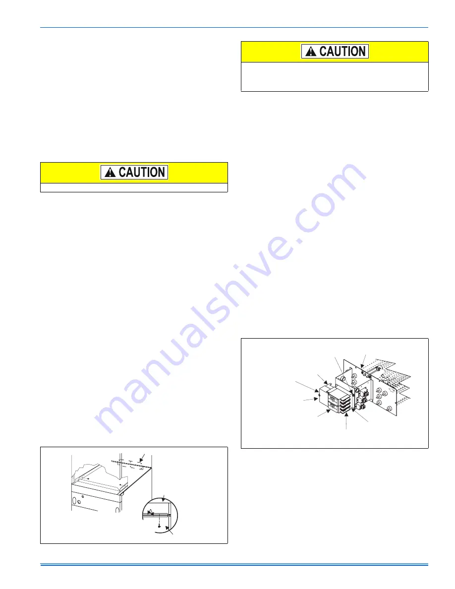
5.
Fasten duct flanges of coil to duct flanges of air handler with
screws. See Figure 6.
6.
Secure toe plate of blower to top panel of coil using 2 screws pro-
vided.
7.
See sections on electrical and blower speed connections.
8.
Re-position and replace access panel.
BLOWER / COIL ASSEMBLY DOWNFLOW
INSTALLATION
1.
Position blower casing over duct connection and secure such that
the supply air end of the blower is down.
2.
Apply neoprene gasket to return-air side of air handler.
3.
Place coil casing over blower return opening.
4.
Align the six holes provided and attach tie plate to back of casings
using screws provided.
NOTE: Tie plate and screws are included with all full cased coils.
5.
Remove blower access panel and coil filter door.
6.
Secure the two toe plates of the blower section and coil using pro-
vided holes and 2 screws.
7.
See sections on electrical and blower speed connections.
8.
Re-position and replace access panel and filter door.
ELECTRIC HEATERS & OPERATING CONTROLS
The low voltage transformer and the CFM board fan / heater control are
standard on all models. The air handlers are shipped pre-wired to oper-
ate as cooling only applications. To complete the installation for cooling
only, install a 6-pin jumper plug to the control board to bypass the
heater limit controls. This jumper plug is secured to the duct cover near
the 4-pin power plug harness. Failure to install the plug will cause the
blower to run continuously. See Figure 10.
Mark the unit nameplate with the appropriate heater selection on the
space provided or NONE to indicate cooling only. To operate these units
with electric heat, it is necessary to field install an electric heater kit
(2HK). See Electric Heater Accessory Installation instructions for proper
installation procedure. Prior to installing electric heat, it is necessary to
perform the following procedure:
1.
Remove the 4-pin power plug from the control board (See Figure
10).
NOTE: This pin must not be used when electric heaters are installed.
2.
Remove the four (4) screws from the duct cover and remove the
duct cover from the air handler.
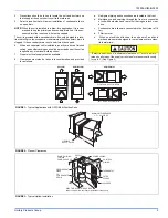
Right-hand Airflow Application Only - Models with Circuit
Breakers
If unit is to be installed for right hand air flow, the circuit breakers in the
heat kit will need to be removed and rotated 180°, so the OFF position
will be down when the cabinet is positioned on the right side. This is an
NEC requirement. Do One Set Of Breakers At A Time - to make sure
wires are reconnected properly. Loosen terminal screws on the wires
and gently pull the wires back from the breaker. Remove screws
securing the breaker plate and rotate 180°, then secure the breaker
plate and reconnect the wires to the breaker. Proper torque for terminal
screws is 35 in/lbs.
LOW VOLTAGE CONTROL CONNECTIONS
The 24 volt power supply is provided by an internally wired low voltage
transformer which is standard on all models. However, if the unit is con-
nected to a 208 volt power supply the low voltage transformer must be
rewired to the 208 volt tap. See the unit wiring label.
Field supplied low voltage wiring can exit the unit on the top right hand
corner or the right hand side panel (see Figure 4, item K).
Install the 7/8" plastic bushing supplied with the unit in the selected hole
and keep low voltage wiring as short as possible inside the control box.
The field wiring is to be connected at the screw terminals of the control
board (Refer to Figures 12, 13, 14, 15, 16, 17, 18, 19, and 20).
Equipment should never be operated without filters.
FIGURE 6: Tie Plate & Fastening Tabs
TIE PLATE
COIL
AIR HANDLER
COIL
TOP PLATE
AIR HANDLER
DOWNFLOW
APPLICATION
UPFLOW & HORIZONTAL
APPLICATIONS
Blowers installed in a downflow application with an electric heater
kit must include a non-combustible floor base if installing on a com-
bustible floor. See instructions for 1FB0617, 1FB0621 and
1FB0624.
FIGURE 7: Electric Heaters in Horizontal Configuration
HEAT KIT
ASSEMBLY
REMOVE 3 SCREWS TO
REMOVE THE CIRCUIT
BREAKER BRACKET
FROM HEAT KIT
ASSEMBLY
JUMPER BAR
JUMPER BAR
COVER
FIELD SUPPLY WIRING
WILL BE ATTACHED TO
THIS SIDE OF THE
CIRCUIT BREAKER(S)
CIRCUIT BREAKER(S) -
THERE MAY BE ONE,
TWO OR THREE
CIRCUIT BREAKER
BRACKET
HEAT KIT WIRING WILL BE
ATTACHED TO THIS SIDE OF
THE CIRCUIT BREAKER(S)
AIR
FLOW


