background image

The Other YN-622C User Guide 


28/08/2013 


Page 4 of 23 

CAMERA COMPATIBILITY 

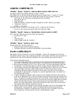
YN-622C “Type A” Camera – Camera Menu Control (2007 and on) 

Provides remote control of flash settings on class 1 flashes: 

Flash Mode (E-TTL with FEC, Manual with global level); Shutter Sync (1

st

 curtain, 2

nd

 curtain, 

HSS/Supersync); Firing groups (E-TTL Ratios, Manual levels); Zoom control; Channels. 

  1D III, 1Ds III, 1D 4. Also ID X but Ratios said to be unreliable. 

  5D II, 5D III, 6D, 7D 

  40D, 50D, 60D 

  450D XSi, 500D T1i, 550D T2i, 600D T3i, 650D T4i (100D, 700D not yet tested) 

  1000D XS, 1100D T3 

  EOS-M (no AF-assist) 

Provides as above except for Firing Groups (E-TTL or Manual) and Channels. 

  G12, G15, G1X, SX20 IS, SX30 IS, SX40 HS, SX50 HS, F335 

YN-622C “Type B” Camera – Flash Button Control (prior to 2007) 

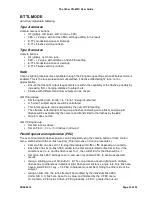
ETTL with FEC, Manual output levels, HSS and Supersync. 

  1D II (Not 1D or 1Ds) 

  5D 

  10D, 20D, 30D 

  300D D-Rebel, 350D XT, 400D XTi 

YN-622C “Type C” Camera - Sync only 

Standard hot-shoe - Synchronised Fire! 

  Supports single-contact hot-shoe cameras. 

  Includes many Nikon and other standard ISO hot-shoe cameras. 

FLASH COMPATIBILITY 

Most flashes with a standard hot-shoe are “compatible” - they can be triggered synchronously. 

(The 622 is rated at only 6 volts on the trigger contact of its hot-shoe. The PC-sync connection can 

withstand 300 volts.) But the YN-622 is bought for its control abilities with a type A camera. 


A bit of relevant Speedlite history - 

1.  There was an Accessory shoe on camera to mount a device, and a centre-pin contact to 

fire the flash. All settings were made on-flash. The camera did not know what they were. 

2.  More pins were added, and TTL, A-TTL, E-TTL and E-TTL II were developed as key flash 

technologies. The camera became more aware of flash settings. Settings still on-flash. 

3.  Canon implemented an off-camera system using a Master flash to drive one or more slaves 

using light-pulse coding. The camera was taught to read the flash settings, and act 

accordingly. FEC was added to the camera. There was no provision on the camera for 

setting Manual output levels, so there was no need to implement a path in the flash's hot-

foot. Settings still on-flash. 

4.  A better interface was required, and in-camera. Canon designed the flash control menus 

(from 1D-III, March 2007 on) so that the camera could both read and set ALL settings in the 

flash. This meant major design requirements for the flashes. All flash settings needed to be 

digital. A path through the flash hot-foot to the processor had to be created which could set, 

not just read the flash settings. They could now be set on-camera for Mark II and later 

flashes. The only flashes which can be fully controlled by flash menus are ones that have 

the required communication through the hot-foot. 

5.  After the release of the YN-622C, Canon released the 5DIII, ST-E3, 1D X and 600EX-RT, 

which provide a “radio wireless” facility. This added features like mixed firing modes 

(ETTL/M/Auto), channels 5-15, Wireless IDs and groups D & E. The 622C cannot use 

these extensions, and the camera must be in “optical wireless” mode. 

Summary of Contents for TOYUG YN-622C

Page 1: ...The Other YN 622C User Guide 28 08 2013 Page 1 of 23 The Other YN 622C User Guide YONGNUO YN 622C E TTL FLASH CONTROLLER AND TRIGGER FOR CANON DSLR CAMERAS Version 3 21 Clive D Bolton 28 August 2013 ...

Page 2: ...stand the technologies can get predictable results The YN 622C is a tool for both approaches One part of Canon s E TTL is often misunderstood Ratios It is more than setting an FEC or EV adjustment on two flash groups That still leaves distance height angle relative powers uneven ambient etc that can make a substantial difference Canon s ratio evaluates the actual contribution to the image of each ...

Page 3: ...Sync Simple Trigger Camera Features Ambient only Shot High speed Continuous Shooting Live View Modelling Light Flash features Flash zoom coverage LCD Display Pilot Indicator 622 Features AF assist beam Sleep Wakeup Status Indicator Group Indicators Using Type B Cameras Using Type C Cameras Suggestions Trouble Shooting Other Resources Specifications Glossary Hot shoe Hot foot Cold shoe The hot shoe...

Page 4: ...ry shoe on camera to mount a device and a centre pin contact to fire the flash All settings were made on flash The camera did not know what they were 2 More pins were added and TTL A TTL E TTL and E TTL II were developed as key flash technologies The camera became more aware of flash settings Settings still on flash 3 Canon implemented an off camera system using a Master flash to drive one or more...

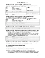
Page 5: ...c Only Synchronised up to 1 8000S Supersync limited by camera and strobe otherwise max 1 250s Includes various hot shoe flashes including single contact flashes A hotshoe flash with only the centre pin effective will receive only a 1st curtain sync signal A flash connected by a PC sync cable including through a PC to Hot shoe adapter will receive a 1st curtain 2nd curtain or pre shutter sync signa...

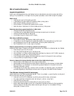
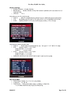
Page 6: ...unction is disabled the firing group consists of All A B C and all groups of flashes use the same global settings Set a channel for the transmitter CH1 CH4 only using the Wireless function menu Confirmation of menu setting When a change to the camera menu is successfully applied to a remote flash the AF Assist Beam of its 622 receiver will flash twice when the Set button is pressed The confirmatio...

Page 7: ...then stay red Release the buttons Factory defaults will be set The defaults will be Flash mode Manual and Sync mode HSS If the unit is then placed on the camera the Flash Control menus will be set to those values Testing the Lighting Setup The setup can be tested to ensure that all devices are powered up and that the communication is working In addition actual lighting outputs can be metered if ma...

Page 8: ...er s Status indicator will flash yellow and its CH and GP indicators will flash green to indicate transmitting The 622 Receivers will flash red and its CH and GP indicators will flash green They will stay in a live update state until the menu session ends Select E TTL II as flash mode When the off camera flash settings match the camera s menu the AF assist beam of the receiver will wink twice to s...

Page 9: ... two Group B flashes with fill from the on top flash FEC and Ratio can be controlled from camera Set one remote 622 to Group B and the other to Group C Set Flash Mode to Manual Set Wireless Firing Group to A B C Set Group Outputs for A 1 32 B 1 8 and C 1 4 Use B as main C as background A as on camera fill Group outputs can be set and adjusted remotely as required Mix Control Mode Creative lighting...

Page 10: ... like the YN 560 Camera menu set to E TTL mode On camera 622 transmitter set to Remote mode On top Class 1 or 2 flash which adopts menu settings to produce an E TTL FEC exposure The 560s set on flash to a manual power level The YN 560s will be triggered at their set levels and will not respond to menu settings The maximum sync speed may be 1 250S Class 5 strobes with Independent Remote Control Dav...

Page 11: ...e Don t have to redo the setting The confirmation light will be emitted only if the remote 622 has C Fn 8 enabled Starting menu item Flash Control or External Speedlite Control First menu Flash Firing Enable or disable the 622 transmitter External flash func setting 622 is identified as an external flash External flash C Fn setting FEB auto cancel locked Enabled FEB sequence locked AF assist beam ...

Page 12: ... Lighting ratio 8 1 to 1 8 plus C with exposure comp 3 to 3 stops Firing Group in Manual flash mode A B C All remotely controllable flashes use Group A 1 1 to 1 128 in 1 3 stops A B Group A output 1 1 to 1 128 Group B output 1 1 to 1 128 Group C not set or fired A B C Group A output 1 1 to 1 128 Group B output 1 1 to 1 128 Group C output 1 1 to 1 128 Setting for group A will also mirror Flash Outp...

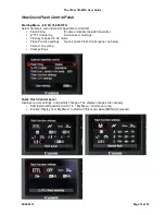
Page 13: ...nsmitter E TTL II metering Evaluative or Average Flash sync speed in AV mode Flash Function settings Opens Quick Flash Control panel as below Flash C Fn setting Clear settings Quick Flash Control panel Displays current settings and permits changes The display changes inter actively Add External Speedlite Control to My Menu and move to top Enable Display from My Menu to start with this menu when ME...

Page 14: ...d light from group A flashes including on top flash and group B flashes will be evaluated by the camera and transmitted to the flashes by the 622 Group C does not fire A B C Firing Group Set A B ratio as above Set an FEC 0 or for flashes in Group C Flash Exposure Compensation FEC The over all automatic flash exposure can be adjusted using the camera button or flash control menu combined with the o...

Page 15: ... cancelled after three shots are taken An E TTL flash which does not support FEB can also be used MANUAL MODE Remote Manual Levels Type A camera menus can remotely control Mk II Speedlites and YN flashes All global groups A and B or A B and C Power levels 1 1 to 1 128 by Group E TTL Flashes do not emit a pre flash All Flashes Global setting Set Flash Mode to Manual Set Flash Output as required 1 1...

Page 16: ...ync in either ETTL or Manual Flash modes including with off camera flashes Not in Multi stroboscopic flash mode Not in Wireless mode and therefore no group functions available Shutter of around 1 30th sec see your camera guide through to Bulb Camera must be in a Creative mode Fast Shutter Sync High Speed HSS or FP ETTL and Manual Flash modes syncs with all shutter speeds up to 1 8000th Sec The cam...

Page 17: ...nel extended 14mm Head in Bounce on Auto mm Head in Bounce on Manual as set Auto adjust for sensor size enabled Zoom Lock An individual flash under remote control can have its zoom setting locked so that it is not controlled by the camera s zoom menu setting Hold down CH SET on a 622 Receiver for several seconds until the channel indicator stays lit This is the same as setting mix control on a tra...

Page 18: ...wink Red Green and the CH and GP indicators will dimly wink also If the voltage becomes low total 2 2 volts the 622 will turn off automatically Batteries can be too low on startup to trigger this action 622 Transmitter communicating green wink 622 Receiver communicating red wink Group Indicators The group LEDs indicate three separate settings at different times Receiver Lighting group briefly on s...

Page 19: ...until the very end Rechargeables at 1 2 volts are already 20 down and approaching the threshold for the 622 Alkaline characteristics are well suited to this type of device with a 60 hour standby time NiMH batteries are great as flash batteries being capable of a rapid discharge into the capacitor Battery Orientation Flashes are often used in low light It can be hard to read the embossed polarity m...

Page 20: ...sabled Umbrella Mount I recommend a lie flat bracket for safety stability and on axis light beam especially for a softbox or umbrella To secure the flash use a Frio Cold Shoe an American product See the blue mounting clip in the images below A home made mount for one flash using a cheap ball swivel and a Frio A two flash adaptation of the single bracket It has two cross bars added and uses a stand...

Page 21: ...l fully charged batteries according to the battery compartment indicators Battery low on startup or half shutter Status will rapidly wink Red Green and the CH and GP indicators will dimly wink also If the voltage becomes low total 2 2 volts the 622 will turn off automatically Batteries can be too low on startup to trigger this action The flash does not fire Ensure the batteries of all devices are ...

Page 22: ... a preflash If the flash s mode is Manual or Multi it won t OTHER RESOURCES Getting the Most from Speedlites Pt 1 10 pages Syl Arena Canon Europe http cpn canon europe com content education technical getting_the_most_from_speedlites do Two excellent books Speedliter s Handbook Learning to Craft Light with Canon Speedlites Syl Arena Peachpit Press Mastering Canon EOS Flash Photography N K Guy Rocky...

Page 23: ...itch Off On CH Set Button 7 channels C1 C2 C3 4 C1 C2 5 C1 C3 6 C2 C3 7 C1 C2 C3 GP Set Button group single A B C combined AB AC BC ABC on Transmitter Group single A B or C on Receiver Test Button press to awaken flash release to fire test flash GP changes group being tested Includes testing via PC port Indicators Status LED Red standby Green operating send receive data 3x Channel LEDs communicati...

Reviews: