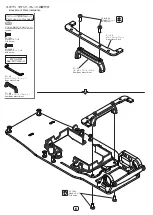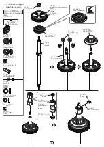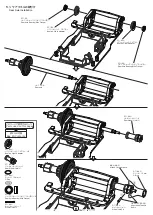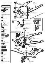
袋 #7 の内容
Bag #7 Contents
このページで使用するパーツ
Parts used on this page
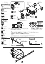
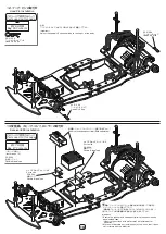
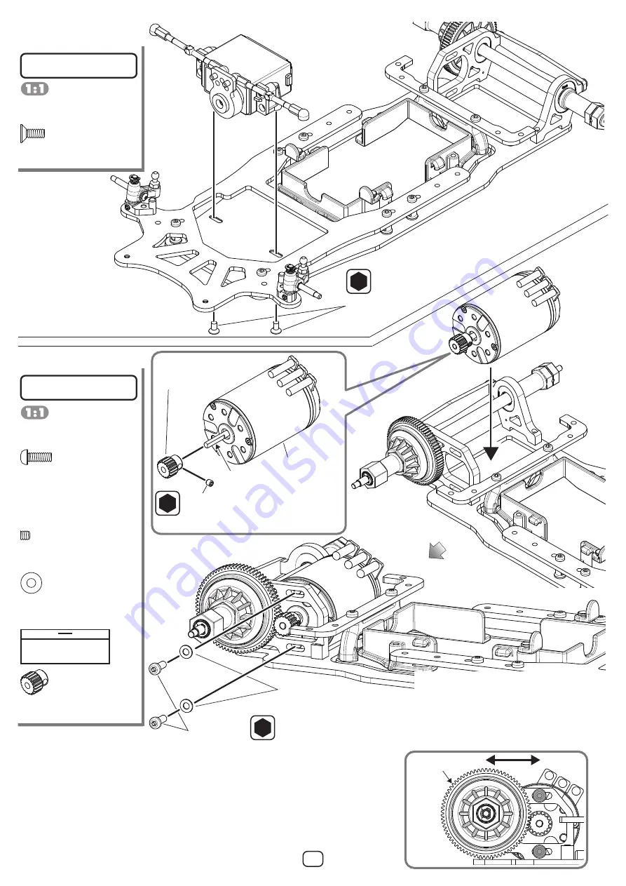
9. サーボの取付け
Servo Installation
ビス袋から必要に応じてお選びください。
Please choose from screw bags as
needed.
セットスクリュー袋から必要に応じて
お選びください。
Please choose from set screw
bags as needed.
ZC-SS33A
M3x3 セットスクリュー ×1
Set Screw
ZC-F38A
M3x8 サラビス ×2
FHS Screw
ZC-BH38-A
M3x8 ボタンヘッド ×2
BHS Screw
BM-4817A
ピニオンギヤ DP48-17T×1
Pinion Gear
このページで使用するパーツ
Parts used on this page
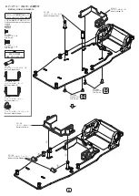
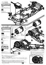
10. モーターの取付け
Motor Installation
ビス袋から必要に応じてお選びください。
Please choose from screw bags as
needed.
ZC-S36A
φ3.1mmxφ6mm/0.5mm
ワッシャー ×2
Washer
注意!
①ピニオンギヤの取り付けはモーターシャフトの D カット されている
部分にセットスクリューが当たる様、しっかりと締め込んで下さい。
②バックラッシュは少し隙間が出来る程度に調整して下さい。
(調整不足はノイズ及びギヤ破損の原因になります。)
③連続走行はモーターに必要以上の負荷を掛けるだけでなく寿命も短くなりますので完全に冷えた事を確認してから走行を
させて下さい。
④リヤホイールが付いていない状態でモーターは回転させないで下さい。ホイルハブピンが飛び出す場合があり大変危険です。
Important!
①Install the pinion so that the set screw is tightened onto the flat portion of the motor shaft.
②Adjust the gear mesh to allow a very small gap between the teeth of the pinion and spur gear.
(Improper adjustment of the pinion and spur gear may result in damage to the gears.)
③Continuous running of the motor will result in shorter motor life. Allow the motor to cool between runs.
④Do not rotate the motor without the rear wheel attached.The wheel hub pin may pop out,
which is extremely dangerous.
スパーギヤ
Spur Gear
ZC-S36A
φ3.1mmxφ6mm/0.5mm ワッシャー
Washer
2.0
ZC-BH38-A
M3x8 ボタンヘッド
BHS Screw
スパーギヤの歯幅にかみ合うようにピニオンギヤの位置を調整し、
セットスクリューを本締めします。
バックラッシュを合わせボタンヘッドビス ( グレー )2 本を本締め
します。
Adjust the position of the pinion gear so that it meshes
with the width of the spur gear, and fully tighten the set
screw.
Adjust the motor position so that the gears mesh
correctly and tighten the two button head screws(Gray)
to secure the motor.
BM-4817A
ピニオンギヤ DP48-17T
Pinion Gear
ZC-SS33A
M3x3 セットスクリュー
Set Screw
1.5
仮止程度に。
Lightly tighten.
モーター
Motor
別途ご用意下さい。
Sold separately.
D カット
Flat portion
2.0
ZC-F38A
M3x8 サラビス
FHS Screw
12
Summary of Contents for GT1
Page 23: ...MEMO ...


