


3
All Rights Reserved. Copyright © 1999, Yokogawa M&C Corporation
IM 77J01Q08-01E
3rd Edition Mar.31,1997-00
IMPORTANT
●
If this instrument is used in a manner not sepecified in
this manual, the protection provided by this instrument
may be impaired.
●
If the product is operated by a power supply exceeding
the specifications, the product may become extremely
hot and, as a result, damaged. To prevent this, ensure
the following before turning on the power.
(a) The voltage of the supplied power and the input
signal level meet the specifications of the product.
(b) External wires are connected to the correct termi-
nals (refer to Chapter 5).
●
Do not operate the product in the presence of flammable
or explosive gases or vapors. To do so is highly danger-
ous.
●
The product is sensitive to static electricity; exercise
care in operating it. Before you operate the product,
touch a nearby metal part to discharge static electricity.
7. DESCRIPTION OF FRONT PANEL
AND CONNECTION OF SETTING
TOOLS
7.1
Front Panel
The communications connector in the front panel is used for set-
ting up parameters through a PC (VJ77 PC-based Parameters Set-
ting Tool) or the Handy Terminal. The ALM1 and ALM2 LEDs
light up if an alarm occus (those LEDs are provided only when the
output-2 is specified for alarm output.)
ALM 1
ALM 2
Alarm output-1 LED
(lights up if an alarm occurs)
Communications connector
Alarm output-2 LED
(lights up if an alarm occurs)
* The LEDs are provided only when output-2
is specified for alarm output.
Fig. 7.1 Front Panel
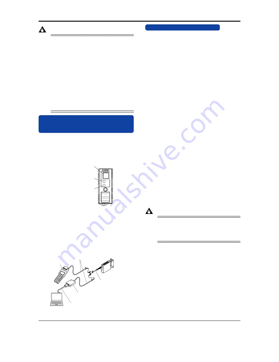
7.2
Connecting the Setting Tools
Connect the modular jack-to-connector adapter (E9786WH) to the
JUXTA communication cable with 5-pin connector (F9182EE)
and then connect this adapter to the communication connector of
JUXTA.
JHT200
Handy Terminal
JUXTA communication cable with
5-pin connectors (F9182EE)
[Provided with VJ77, JHT200]
Modular jack conversion
adapter (E9786WH)
[Provided with VJ77]
Dedicated adapter (E9789HA)
[Provided with VJ77]
Dedicated cable (E9786WK)
[Provided with VJ77]
PC
Fig. 7.2 Connecting the Setting Tools
8. SETTING PARAMETERS
Set the parameters using a PC (VJ77 PC-based Parameters Setting
Tool) or the Handy Terminal. Refer to the list of parameters in this
manual and the Instruction Manual for Handy Terminal (IM JF81-
02E) and VJ77 PC-based Parameters Setting Tool (IM 77J01J77-
01E).
8.1
Settings Related to Inputs and Outputs
8.1.1 Input Range Unit
When referring and setting the input range, select and set "Hz" or "kHz"
in D10: UNIT. Select "kHz" when input range is over 32000Hz.
8.1.2 Conversion Mode
Select and set the action of the instrument from "F/V CON-
VERTER" (F/V conversion) or "INTEGRATOR" (pulse integra-
tor) in D19: SELECT MODE.
F/V converter: Set when converting 0 to 100% of frequency input
to 0 to 100% of analog output, and outputting it.
INTEGRATOR: Set when converting 0 to 100% of frequency in
put to 0 to 100% of analog output after comput-
ing the average frequency from the pulse number
integrated per sample time, and outputting it.
8.1.3 Sample Mode
Select and set "AUTO" or "MANUAL" in D20: SAMPLE MODE,
when the conversion mode is set to "INTEGRATOR."
AUTO: Outputs the sample time forcibly on the provided conditions.
MANUAL: Sets the sample time within setting range.
8.1.4 Sample Time
When the sample mode is set to "MANUAL", set the sample time
in numerical value in D21: SAMPLE TIME,
Sample time setting range: 0.1 to 100 seconds, by 0.1 second
When the sample mode is set to "AUTO", the sample time is forc-
ibly decided on the following conditions.
0.1 second when F
100
(100% input frequency) is 1kHz or more
(1/F
100
)
⫻
100 seconds when F
100
is over 1Hz and below 1kHz
100 seconds when F
100
is 1Hz or less
8.1.5 Input Range
Set the 0% value of input range in D22: INPUT1L_RNG, and
100% of input range in D23: INPUT1H_RNG within the numeri-
cally specified range.
IMPORTANT
In case the input range is changed after factory-ship, the in-
strument may not work within the rated accuracy range de-
pending on the changed input range. Perform the adjustment
following the maintenance of this instruction manual after
changing the input range.
8.1.6 Input Filter
When the chattering noise is generated in input, the input filter is
used to restrain the influence. Select and set "ON" in D50: INPUT
FILTER, then the input filter for time constant of about 10ms will
be connected.
8.1.7
Direction of Output Action
Analog output signals can be reversed. To reverse the signal from
output-1, set D38: OUT1 DR to REVERSE. For output-2, set D39
OUT2 DR to REVERSE. To return the output-1 signal to normal,
set D38: OUT1 DR to DIRECT. For output-2, set D39: OUT2 DR
to DIRECT.


