


24
IM 04P02B01-02E
Common Operations and Menu Structure
The character type changes each time you press the
CHARACTER
(
MENU
) key. The
character type changes in reverse order each time you press the
SHIFT
(
FEED
) +
CHARACTER
(
MENU
) key.
The character types change in the following order: uppercase alphabet (
A-Z
), lowercase
alphabet (
a-z
), numbers (
0-9
), and symbols (
%-.
).
A-Z
A to Z, and space
a-z
a to z, and space
0-9
0 to 9, and space
%-.
%, #,
°
, @, +,
−
, *, /, (, ),
µ
,
Ω
,
2
,
3
, ., and space
The character changes each time you press the
(
DISP
) key. The character changes
in reverse order each time you press the
SHIFT
(
FEED
) +
(
DISP
) key.
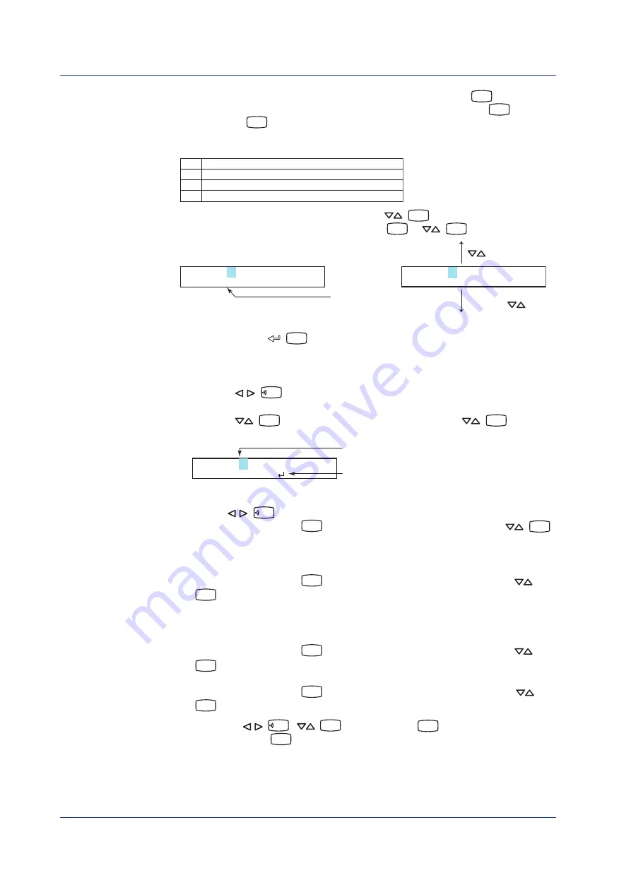
Character type
Unit=ppm
CHR:a-z
SHIFT key +
key
key
Unit=ppm
CHR:a-z
p
o
n
l
k
j
You repeat these steps to enter the character.
When you press the
(
CH UP
) key, the change is applied and the next screen is
displayed.
• Inserting a Character
Press the
(
FUNC
) key to move the cursor to the position where the character is to
be inserted.
Press the
(
DISP
) key to show
Ins DISP
and then press the
(
DISP
) key. A
space for one character is inserted. Enter the character.
Position to insert the character
Display Ins DISP
Unit=ppm
CHR:Ins DISP
• Deleting a Character
Use the
(
FUNC
) key to move the cursor to the character to be deleted.
Press the
CHARACTER
(
MENU
) key to show
Del DISP
and then press the
(
DISP
)
key. The character is deleted.
• Deleting an Entire Character String
Press the
CHARACTER
(
MENU
) key to show
Clear DISP
and then press the
(
DISP
) key. The entire character string is deleted.
• Copying & Pasting a Character String
Show the copy source character string.
Press the
CHARACTER
(
MENU
) key to show
Copy DISP
and then press the
(
DISP
) key. The character string is saved to the memory.
Show the copy destination.
Press the
CHARACTER
(
MENU
) key to show
Paste DISP
and then press the
(
DISP
) key. The character string is pasted.
*
When the
(
FUNC
),
(
DISP
), or
CHARACTER
(
MENU
) key is pressed while holding
down the
SHIFT
(
FEED
) key, the operation is reversed as when the respective key is pressed
by itself.