


12
IM 04L55B01-02EN
Configuring the GM via USB
Communication
In the case of USB communication, use the Hardware
Configurator (hereafter refer to as the software). For details
on the features and operating procedures of the software, see
the S STANDARD Hardware Configurator User’s
Manual (IM 04L61B01-02EN).
1. Connect a cable to the GM10 USB port (mini B type) to
communicate with the PC. Connect using the following
communication conditions.
Baud rate: 115200, parity: none, data length: 8 bits,
stop bits: 1 bit, handshake: off:off
Make sure that the PC is connected to the Internet. A USB
driver will be downloaded automatically.
2. Start the software.
Reconfiguring (Module identification)
1. On the menu bar, click the
Operation
tab and then
Reconfiguration
.
A Communication [Reconfiguration] dialog box appears.
2. Enter the information, and click
OK
.
You can check the port USB number using Windows
Device Manager.
3. When a confirmation dialog box appears, click
OK
. A
reconfiguration completion dialog box appears.
4. Click
OK
.
Configuring Various Items
For details on settings, see the Web application.
Send Settings
Receive Settings
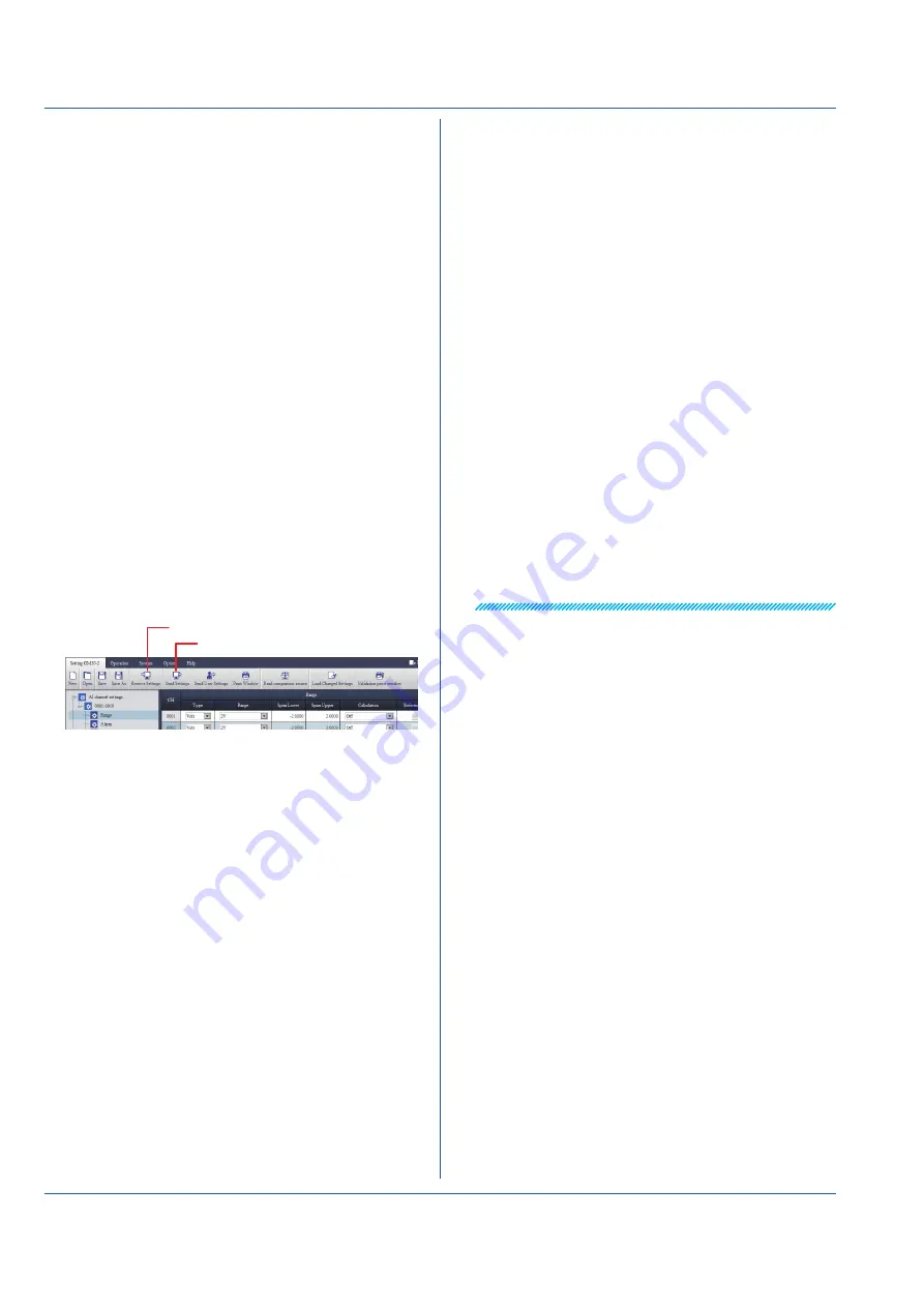
1. On the menu bar, click the
Setting
tab and then
Receive
Settings
.
2. When a Communication [Reconfiguration] dialog box
appears, click
OK
.
The setup data of the connected GM will appear.
3. Set the items.
4. On the menu bar, click the
Setting
tab and then
Send
Settings
.
5. When a Communication [Reconfiguration] dialog box
appears, click
OK
.
The setup data will be sent to the connected GM.
You can also save the setup data to be sent later.
Starting to Measure and Record
Starting from the Web Browser
From the Web Application
1. On the menu bar, click the
S Web Service
tab
and then
Recording
.
2. When a Recording dialog box appears, click
Start
recording
. Recording will start.
• To stop recording, in step 2 above, click
Stop recording
.
From Hardware Configurator
1. On the menu bar, click the
Operation
tab and then
Start
Recording
.
2. When a Communication [Reconfiguration] dialog box
appears, click
OK
. Recording will start.
• To stop recording, in step 2 above, click
Stop Recording
.
Starting with the GM10 START Key
Hold down the START key on the GM10 front panel for at
least 2 seconds.
Recording will start, and “REC” in the GM10 status display
area will light in green.
• Stopping the Recording
Hold down the STOP key for at least 2 seconds. The
“REC” indicator will turn off.
• The “REC” LED also turns on and off when recording is
started and stopped from the Web application or Hardware
Configurator.