


IM 77J04R31-01E 2nd Edition Oct. 15, 2019-00
6
The previously adjusted value
will be reset.
The decimal point blinks during
data change.
This causes parameter "AH" and the measured value to
appear alternately.
Press the UP or DOWN key.
The decimal point blinks.
Press the SET/ENT key.
The value before adjustment (153.9) appears on the DATA
display.
This completes the input adjustment for the MVRK.
Press the SET/ENT key to display parameter "RST."
Press the UP key to display "ON" on the DATA display.
Press the SET/ENT key.
This resets the previously adjusted value.
Setup Parameter Screen 2
Using the 6-dial variable resistor, apply resistance equivalent
to the input 150°C to the MVRK.
If additional re-adjustment must be made, take the following steps and then perform the
procedure above.
Press to display
"RST."
Press to display
"ON."
Press .
This completes the input
adjustment.
The decimal point blinks.
The measured value and
parameter AH are displayed
alternately.
Press or .
Press .
11. SETTING ACTIVE COLOR PV DISPLAY (PV DISPLAY COLOR
CHANGING FUNCTION)
11.1 Setting Ranges and Factory-Set Values
Setup Parameter Screen 1
Parameter
Symbol
Parameter Name
Setting Range
Factory-Set
Value
High limit for PV display
color change (PCH)
When PV display color mode (PCM) is 6 or 7: PCL+1digit
to 9999
When PV display color mode (PCM) is 8 or 9:
-100.0 to 100.0% of the measured input range
* The setting range depends on the setting of the decimal
point position (SDP).
−
Low limit for PV display
color change (PCL)
When PV display color mode (PCM) is 6 or 7:
-1999 to PCH-1digit
When PV display color mode (PCM) is 8 or 9:
-100.0 to 100.0% of the measured input range
* The setting range depends on the setting of the decimal
point position (SDP).
−
Setup Parameter Screen 2
Parameter
Symbol
Parameter Name
Setting Range
Factory-Set
Value
PV display color mode
(PCM)
0: Fixed in green
1: Fixed in red
2: Link to alarm 1
(under normal condition: green; at alarm status: red)
3: Link to alarm 1
(under normal condition: red; at alarm status: green)
4: Link to alarm 1 and alarm 2
(under normal condition: green; at alarm status: red)
5: Link to alarm 1 and alarm 2
(under normal condition: red; at alarm status: green)
6: PV limit*
(when more than PCL, less than PCH: green; when
PCL or less, PCH or more: red)
7: PV limit*
(when more than PCL, less than PCH:red; when PCL
or less, PCH or more: green)
8: SP deviation*
(when more than SP-PCL, less than SP+PCH: green;
when SP-PCL or less, SP+PCH or more: red)
9: SP deviation*
(when more than SP-PCL, less than SP+PCH: red;
when SP-PCL or less, SP+PCH or more: green)
10: Link to alarm 1 to alarm 4
(under normal condition: green; at alarm status: red)
11: Link to alarm 1 to alarm 4
(under normal condition: red; at alarm status: green)
1
*: PV display color is changed linking to the setting range of high limit (PCH) and low limit (PCL) for PV display
color change.
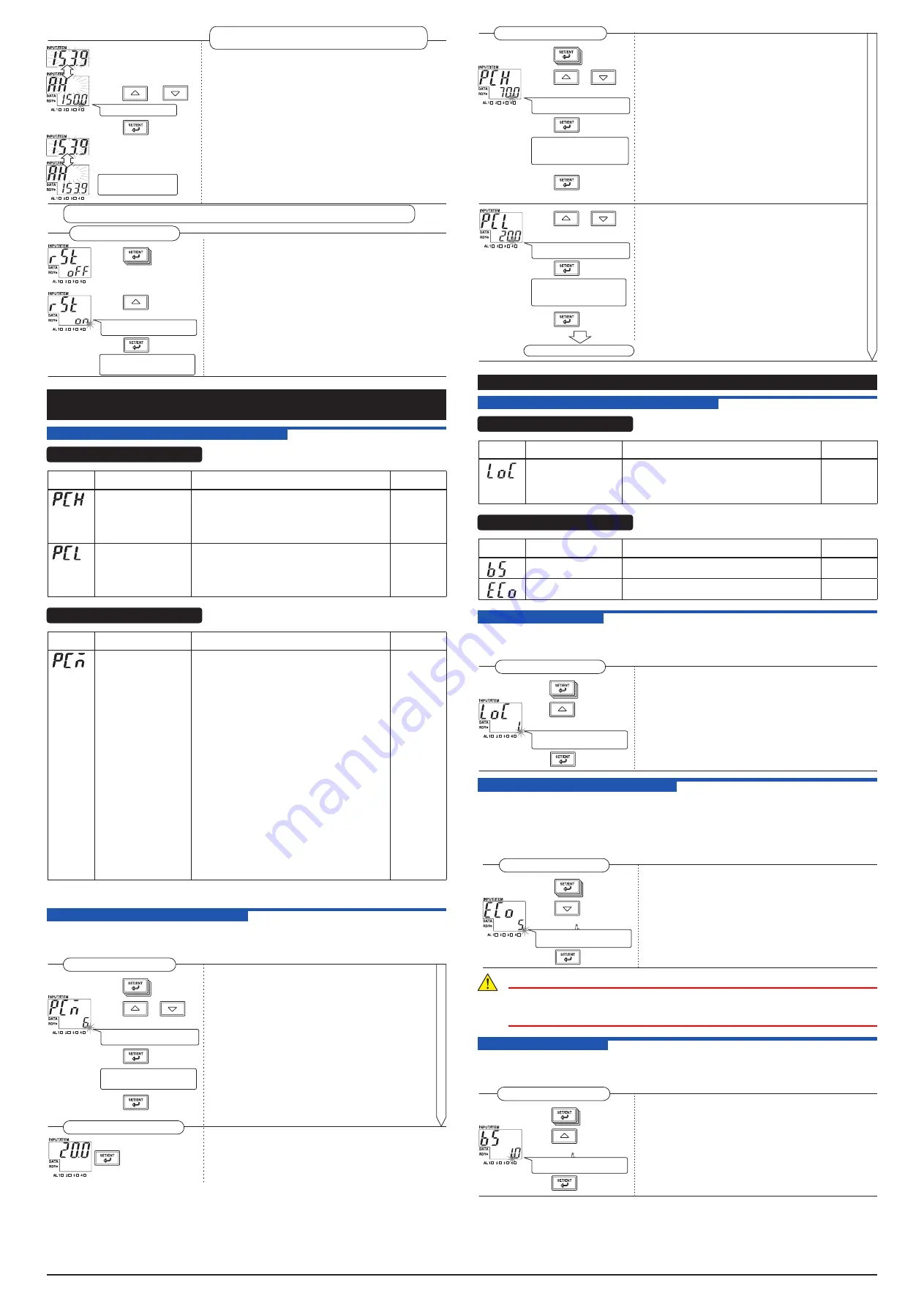
11.2 Setting Active Color PV Display
This section describes an example of setting the PV display color mode (PCM) to “6,” high limit for
PV display color change (PCH) to “70.0” and low limit (PCL) to “20.0.”
The procedure below begins with the condition in which the Setup Parameter Screen 2 is displayed.
When you press the SET/ENT key for more than 3 sec.
with the Operation Parameter Screen displayed, the Setup
Parameter Screen 1 appears.
Press this key for
more than 3 sec.
Operation Parameter Screen
Press the SET/ENT key to display parameter "PCM."
Press the UP or DOWN key to display "6" on the DATA
display.
The decimal point blinks during
data change.
This completes the process for
setting the PV display color mode.
Press to display
"PCM."
Press or
to display "6."
"
Press .
Press for more
than 3 sec.
Press the SET/ENT key to accept PV display color
mode "6."
Press the SET/ENT key for more than 3 sec.
This causes the Operation Parameter Screen to appear.
Setting the PV display color mode
Setup Parameter Screen 2
Continue to the upper right
Press the SET/ENT key to display parameter "PCH."
Press the UP or DOWN key to display "70.0" on the DATA
display.
The decimal point blinks during
data change.
This completes the process for
setting the high limit for PV display
color change.
Press to display
"PCH."
Press or
to display "70.0."
Press .
Press to display
"PCL."
Press the SET/ENT key to accept the high limit for PV
display color change "70.0."
Press the SET/ENT key to display parameter "PCL."
Press the UP or DOWN key to display "20.0" on the DATA
display.
The decimal point blinks during
data change.
This completes the process for
setting the low limit for PV display
color change.
Press or
to display "20.0."
Press .
Press for more
than 3 sec.
Press the SET/ENT key to accept the low limit for PV
display color change "20.0."
Press the SET/ENT key for more than 3 sec.
This causes the Operation Parameter Screen to appear.
Setting the high and low limits for PV display color change
Setup Parameter Screen 1
To the Operation Parameter Screen
12. OTHER PARAMETERS
12.1 Setting Ranges and Factory-Set Values
Setup Parameter Screen 1
Parameter
Symbol
Parameter Name
Setting Range
Factory-Set
Value
Key lock
(LOC)
0: Without lock. All parameters can be set.
1: Parameters other than the operation parameters
cannot be changed.
2: All parameters cannot be changed.
-1: This moves to the Setup Parameter Screen 2.
0
Setup Parameter Screen 2
Parameter
Symbol
Parameter Name
Setting Range
Factory-Set
Value
Measured input bias (BS) -1999 to 9999
0
Economical mode time
(ECO)
0 (Continuous: no display OFF function), 1 to 60
(minutes)
10
12.2 Setting Key Lock
This section describes an example of locking keys so that parameter settings other than the
operation parameters cannot be changed. The procedure below begins with the condition in which
the Setup Parameter Screen 1 is displayed.
Press the SET/ENT key to display parameter "LOC."
Press the UP key to display "1" on the DATA display.
Press the SET/ENT key to accept this data.
The decimal point blinks during
data change.
Setup Parameter Screen 1
Press to display
"LOC."
Press to display
"1."
Press
12.3 Setting Economical Mode Time
Setting economical mode time allows indications on the PV display to be extinguished if no keystroke
is made within the set time.
The MVRK’s power consumption in the OFF mode is approximately 0.5 W or 1 VA during normal
operations (non-alarm status). This section describes an example of setting the economical mode
time to “5 minutes” (factory-set value: 10 minutes).
The procedure below begins with the condition in which the Setup Parameter Screen 2 is displayed.
Press the SET/ENT key to display parameter "ECO."
Press the DOWN key to display "5" on the DATA display.
Press the SET/ENT key to accept this data.
The decimal point blinks during
data change.
Setup Parameter Screen 2
Press to display
"ECO."
Press to display
"5."
Press .
CAUTION
The economical mode is temporarily released at the time of PV display color change
and the PV display lights up. After the set economical mode time elapsed from the time
of returning to normal operation, the economical mode operation begins again .
12.4 Setting Input Bias
This section describes an example of correcting an error by setting input bias if there is an error of “-1
(°C)” in the MVRK displayed value with respect to the measured value. The procedure below begins
with the condition in which the Setup Parameter Screen 2 is displayed.
Press the SET/ENT key to display parameter "BS."
Press the UP key to display "1.0" on the DATA display.
Press the SET/ENT key to accept this data.
The decimal point blinks during
data change.
Setup Parameter Screen 2
Press to display
"BS."
Press to display
"1.0."
Press .


