3
IM 77J08P01-01EN 1st Edition
2017.10.30-00
Power Supply and Isolation
Power supply voltage: 24 V DC ±10% (percentage ripple: less
than 5% p-p)
Current consumption:24V DC 60 mA
Insulation resistance: 100 MΩ at 500 V DC between input and
output, output and power supply, and input and
power supply.
Withstand voltage: 1500 V AC/min. between input and (output
and power supply)
500 V AC/min. between output and power supply.
4. SETTING THE LOAD RESISTANCE FOR
CURRENT PULSES AND THE INPUT FILTER
If the signal from the generator is a current pulse, it needs to be
converted into voltage using load resistance for current pulses.
Further, if the input contains chattering noise and the like, you can
set an input filter to suppress its effect.
z
The load resistance and filter are set using a DIP switch (SW1)
inside the product.
4.1 SETTING THE LOAD RESISTANCE
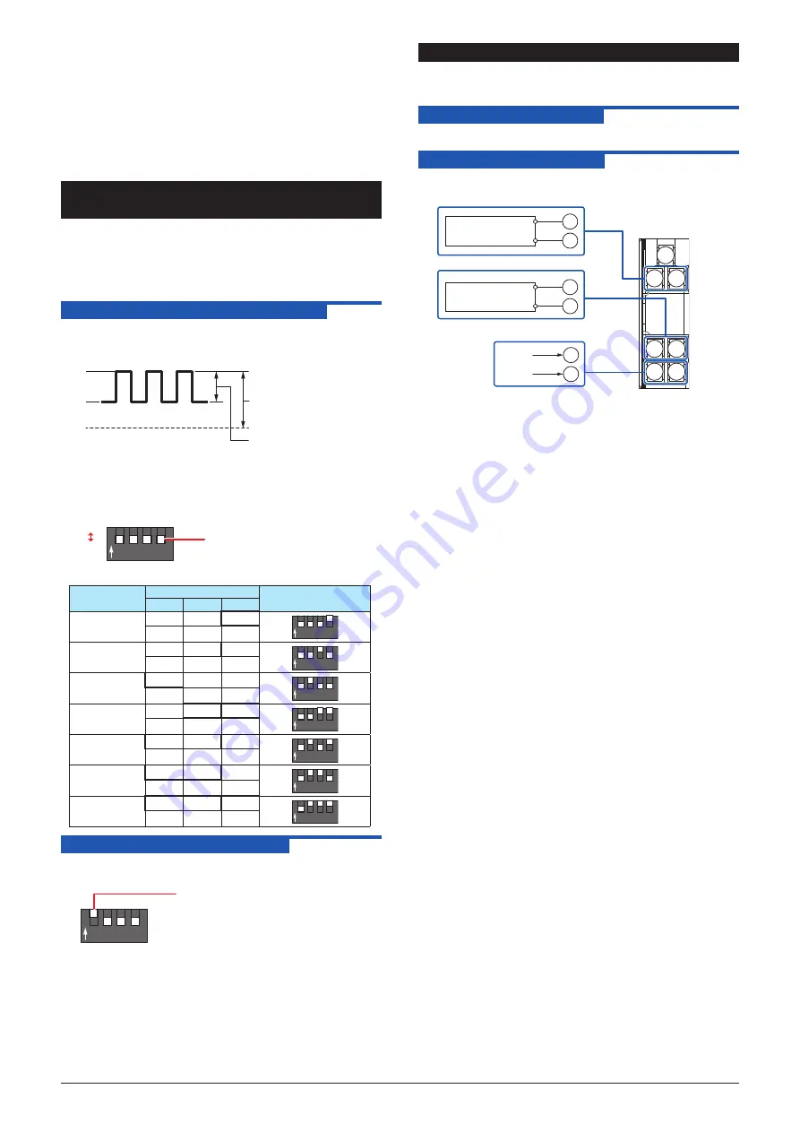
Set the load resistance so that the relationship between the peak
current i (p-p) from the generator and the combined load resis-
tance RL satisfies the following: swing width i × RL ≥ 3V.
EL
EH
24 V or less
(peak value)
EH – EL = 3 V or more
(swing width)
0V
Set the resistance by turning on or off the DIP switch (SW1-2,
SW1-3, SW1-4).
When the SW1 settings are all off
1 2 3 4
ON
Use a pointed object to flip
the switches between on
and off.
SW1
ON
OFF
Resistance
value
SW1
DIP switch setting
2
3
4
200 Ω
ON
1 2 3 4
ON
OFF
OFF
510Ω
ON
1 2 3 4
ON
OFF
OFF
1kΩ
ON
1 2 3 4
ON
OFF
OFF
144Ω
ON
ON
1 2 3 4
ON
OFF
167Ω
ON
ON
1 2 3 4
ON
OFF
338Ω
ON
ON
1 2 3 4
ON
OFF
126Ω
ON
ON
ON
1 2 3 4
ON
4.2 SETTING THE INPUT FILTER
Set SW1-1 to ON. An input filter with a time constant around 10
ms will be connected.
1 2 3 4
ON
ON
z
If the input filter is set to ON, the input frequency will be limited
to no more than 100 Hz and the pulse width to no less than 3
ms.
5. MAINTENANCE
The product starts running immediately when the power is turned
on; however, it needs 10 to 15 minutes of warm-up before it
meets the specified performance.
5.1
Calibration Apparatus
z
A calibrator (YOKOGAWA CA150 or equivalent)
5.2
Calibration Procedure
1. Connect the instruments as shown below.
1
2
3
4
5
6
7
2
3
6
7
Calibrator
Calibrator
24 V DC
Power supply
Input
Output
+
−
+
−
+
−
4
5
2 Apply a calibrator-generated rectangular pulse at any frequency
within the specifications to the input.
3. Measure the output with the calibrator, and check that the pulse
frequency is the same as the input frequency.
Summary of Contents for JUXTA F Series
Page 4: ...Blank Page ...


