background image

6

IM XL120P

3.

Names and Functions of Parts

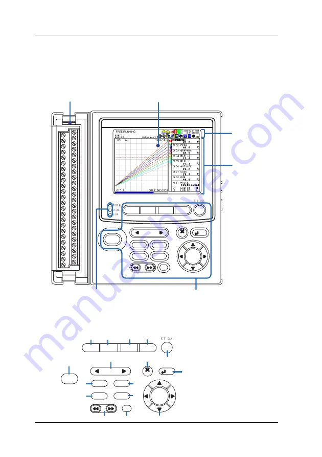
Front Panel

HOME

REVIEW

FILE

SETTING

HOLD

TIME / DIV

SAVE

RANGE

DISPLAY

GROUP

MARK

SET

ESC

SELECT

START
/ STOP

Display

Displays measured data, operation 
status, setup menu, settings, etc.

Terminal block unit

Terminal block unit where 
probes are connected.

Keys

Operation status LED

POWER :  Illuminates when the power is ON
CHARGE :  Illuminates when the battery is being charged
START :  

Illuminates while logging

Status display 
section

Data display, 
setting menu, 
and setting 
display section

For the wiring procedure, 
see page 23.

For the viewing the displays, 
see page 9.

Keys

HOME

REVIEW

FILE

SETTING

HOLD

TIME / DIV

SAVE

RANGE

DISPLAY

GROUP

MARK

SET

ESC

SELECT

START
/ STOP

1

2

3

4

5

6

7

8

9

11

10

12

13

14

15

16

Summary of Contents for Datum Y XL100

Page 1: ...Datum Y Quick Setup Manual IM XL120P IM XL120P 1st Edition Apr 2007 YMI XL111 XL112 XL114 Datum Y XL121 XL122 XL124 Datum Y XL111 XL112 XL114 Portable Data Logger Datum Y XL121 XL122 XL124 Portable D...

Page 2: ...only for the Portable Data Station After reading this manual keep it in an easily accessible place for later reference This manual will come in handy when you are unsure of how to operate the product...

Page 3: ...and in this manual WARNING Indicates a hazard that may result in the loss of life or serious injury of the user unless the described instruction is abided by CAUTION Indicates a hazard that may result...

Page 4: ...Setting Mode 22 Key Operations for Entering Characters 23 Key Operations for Entering Values 23 7 Signal Wiring 24 8 Connecting to the Power Supply and Turning the Power Switch ON OFF 26 Connecting th...

Page 5: ...Model When inquiring about the product to the vender please also give the vendor this number Accessories Make sure that the package contains all the accessories listed below and that they are all fre...

Page 6: ...e data Free Running Mode Logging Mode Set the language Initial startup only Analyze the data Review Mode Logging Review Mode Process the file as necessary Rename the file Delete the files Copy the dat...

Page 7: ...e probes are connected Keys Operation status LED POWER Illuminates when the power is ON CHARGE Illuminates when the battery is being charged START Illuminates while logging Status display section Data...

Page 8: ...to cancel a key operation 8 SET Key Press this key to set settings entered through the keys 9 START STOP Key Press this key to start stop logging 10 RANGE Key Press this key to change the input range...

Page 9: ...iption see section 3 5 For a description see section 3 4 For a description see section 3 8 For a description see section 3 8 For a description see section 4 1 For a description see section 3 6 Digital...

Page 10: ...d Red Alarm activated 5 Alarm Output Status The status is displayed using different icon colors for each alarm output channel 1 to 4 as follows Gray No alarm setting Yellow green Alarm setting enabled...

Page 11: ...o DIVISION The icon blinks when there is access to the CF card An icon shown when the data save destination is set to CF card and the memory full operation is set to REPEAT The icon blinks when there...

Page 12: ...wn when the interface is set to USB For other cases the icon is gray Supported only on the XL121 XL122 and XL124 An icon shown when the communication protocol is set to Modbus slave The icon is gray w...

Page 13: ...selected channel active channel 4 Scale Upper Limit Shows the display upper limit of the active channel 5 Scale Lower Limit Shows the display lower limit of the active channel 6 Pen Displayed at the...

Page 14: ...ters 12 Channel No Tag Displays the channel number and the specified tag up to 8 characters The active channel is shown highlighted reverse video Other Data Displays In addition to the waveform digita...

Page 15: ...gging Review Display Displays both the waveforms of data currently being logged and the waveforms of data saved in the past Alarm Summary Display Displays the alarm status in a list Log Display Displa...

Page 16: ...mocouple Selectable from the following types R S B K E J T N W L and U RTD Selectable from Pt100 and JPt100 types Pulse signal Displays the pulse input as number of revolutions integrated value or ins...

Page 17: ...ter than or equal to the alarm value Lo An alarm occurs when the measured calculated value is less than or equal to the alarm value Window IN An alarm occurs when the measured calculated value is with...

Page 18: ...rigger on the next page occurs The logging data contains alarm information Manual sampled data The measured calculated data instantaneous values of all channels can be saved by pressing the SAVE key i...

Page 19: ...ecified time Timer The time at which the data save operation is stopped can be specified Logging is stopped after the specified time elapses File Operations The following file operations are available...

Page 20: ...data on the external storage medium or internal memory of the XL100 PC Ethernet FTP server Hub Hub Automatically save measured data Load measured data FTP client Ethernet Hub Hub FTP server Web Serve...

Page 21: ...nterface The Modbus master function enables the measured data of a measuring instrument connected as a Modbus slave to be retrieved as communication input data The data can be assigned to a communicat...

Page 22: ...6 Setting Mode in which various settings such as the measurement conditions are specified The keys in the figure below are used to switch between these modes HOME REVIEW FILE SETTING START STOP Review...

Page 23: ...and press SELECT DISPLAY SELECT Display the menu Select the display Confirm the display Switching the menu in Setting Mode Press the arrow keys to select the desired item and press SELECT A selection...

Page 24: ...n area Character type selection area A alphabet characters 0 numeric characters and symbols Backspace Delete Key Operations for Entering Values For settings that require a value to be entered a value...

Page 25: ...de noise voltage 30 VACrms 50 60 Hz or 60 VDC Wiring Procedure 1 Open the terminal cover of the terminal block unit 2 Wire the input signal cables to the input terminals As shown below loosen the term...

Page 26: ...1 5 mm2 AWG 26 to 14 Length of the stripped section of the wire Approx 7 mm Input signal wires whose diameter is 0 3 mm or less may not be securely fastened Fold over the conducting section of the wi...

Page 27: ...power cord Connecting the AC Adapter Follow the steps below to connect the AC adapter 1 Check that the power switch is OFF 2 Connect the AC adapter to the AC adapter jack of the XL100 3 Connect the p...

Page 28: ...er When attaching the accessory side cover fasten the side cover attachment screw to fix the cover to the XL100 Side cover Power switch cover Side cover attachment screw Rubber boot Open from this end...

Page 29: ...ou set the language the XL100 will start up using the specified language the next time 1 When you turn the power switch ON the following screen appears 2 Use the arrow keys to select the language and...

Page 30: ...0 0 to 1000 0 C is input to CH1 The settings of other input channels are not changed from the default settings For details on setting the input channels see chapter 5 Setting the Input Channels in th...

Page 31: ...30 IM XL120P SELECT Keys Display SELECT 5 6 7 8 Show the CH01 setting screen Show the MODE selection list Move the cursor to TC 9 SELECT Select TC Move the cursor to MODE 9 Setting the Input Channel...

Page 32: ...31 IM XL120P SELECT Keys Display 10 11 12 Move the cursor to RANGE Show the RANGE selection list Move the cursor to E 13 SELECT Select E 14 Move the cursor to SPAN LOWER 9 Setting the Input Channel...

Page 33: ...ay SELECT 15 16 Show the SPAN LOWER entry window Enter 0 0 17 SET Set SPAN LOWER settings To perform measurement To configure other settings HOME SETTING 18 SET The changed settings are confirmed 9 Se...

Page 34: ...et to timer seven days later The settings for saving other measured data are not changed from the default settings For details on the settings for saving measured data see section 9 1 Setting the Save...

Page 35: ...L120P 5 SELECT 6 7 Move the cursor to 1 min Select 1 min Move the cursor to SAVE MEDIA 8 SELECT Show the SAVE MEDIA selection list 9 Move the cursor to CF CARD Keys Display 10 Setting the Data Save Op...

Page 36: ...10 11 Confirm CF CARD Move the cursor to TRIGGER 12 SELECT Show the TRIGGER setting screen 13 Move the cursor to END TRIGGER Keys Display SELECT 14 Show the END TRIGGER setting screen 10 Setting the...

Page 37: ...5 16 SELECT Show the TRIGGER TYPE selection list 17 Move the cursor to TIMER Keys Display SELECT 18 Select TIMER 19 Move the cursor to TIMER SELECT Show the TIMER SETTINGS window 10 Setting the Data S...

Page 38: ...20P 20 21 Enter 0168 00 00 Keys Display SET Set END TRIGGER settings To perform measurement To configure other settings HOME SETTING 22 SET The changed settings are confirmed 10 Setting the Data Save...

Page 39: ...ting Mode and check that the input settings are correct If the measured values are not correct even though the input settings are correct see chapter 14 Troubleshooting If the CF Card icon is gray the...

Page 40: ...e External Storage Media in the User s Manual Inserting or Removing a CF Card Insert the CF card firmly into the CF card slot on the side panel of the XL100 To remove the CF card press the CF card eje...

Page 41: ...name YYMMDDhhmmss DLO YY year MM month DD day hh hour mm minute ss second is automatically assigned to measurement data files YYMMDDhhmmss CSV if the data type is set to ASCII You can also assign an...

Page 42: ...sured data saved to a CF card is given below TIP If you press REVIEW in Logging Mode the XL100 switches to Logging Review Mode see page 21 SELECT Keys Display 1 3 4 2 Change to Review Mode Show the LO...

Page 43: ...7 Move the cursor to the file shown in the FILE area Select the file Keys Display SET The file is loaded and the data is displayed as shown in the figure on the right Select CF CARD SELECT 13 Analyzin...

Page 44: ...ct marker A and B alternately The selected marker active marker is displayed with a thick line Moving the Marker Press the left or right arrow key Hold the key down to move the marker quickly Moving t...

Page 45: ...that the key lock is not shown at the upper right corner of the display Unable to save load from the Turn the power switch OFF and then back internal memory ON It may be restored by the power on self...

Page 46: ...4 active channel 12 active marker 43 alarm 16 18 alarm data 17 alarm function 16 alarm line 12 alarm output status 9 alarm status 9 alarm summary display 14 arrow keys 7 B backup file 17 backup memor...

Page 47: ...21 43 RS 232 8 20 RS 485 8 20 RTD 15 25 S sampling interval 9 33 SAVE key 7 save setting data 18 saved data file loading of 41 scale 12 screen image data 17 SD card 10 39 SELECT key 7 serial communic...

Page 48: ...47 IM XL120P W waveform 12 Web server 19 Index...

Page 49: ...48 IM XL120P Memo...

Page 50: ...49 IM XL120P Memo...

Page 51: ...50 IM XL120P Memo...

Reviews: