<6. Operation>
13
IM 01E21A01-03EN-A
● Setting of Write Protect Switch
The write protect function is to prevent the overwriting of
parameters.
Write protection can be carried out using either the write
protection switch (SW1-2) (See Figure 6.3.1) or software
function with parameter setting. If either of these items is
activated, the overwriting of parameters will be prohibited.
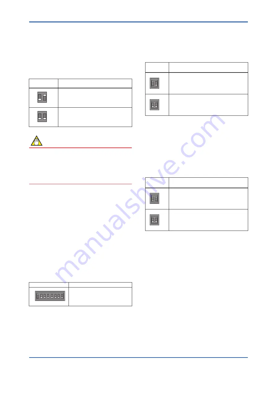
Table 6.3.1
Write protect switch (SW1-2)
Position of
Switch
Description
1
2
ON
OFF
SW1
H
L
Write protect: ON
Parameters cannot be overwritten
1
2
ON
OFF
SW1
H
L
Write protect: OFF
Parameter can be overwritten.
NOTE
• If the hardware switch is set to “ON”, the condition
of preventing parameter overwriting kept until the
switch is set to “OFF”.
• For the software write protect, read the user’s
manual of applicable communication type as listed
in Table 1.1.
● Setting of Address Switch (ADDRESS)
The device IP address can be set using either the
address switch (ADDRESS) (See Figure 6.3.2) or
software parameters.
The Address Switch (ADDRESS) is used to set the 4
th
octet (8 bits) of the IP address. The 1
st
, 2
nd
and 3
rd
octets
of the IP address are set by software parameters. The
4
th
octet of the address which is set by this switch
(ADDRESS) is enabled when the Enable hardware
switch (SW3-1) is set to ON. When the Enable hardware
switch (SW3-1) is set to OFF, the 4
th
octet of the IP
address set by this switch (ADDRESS) is disabled, and
the 4th octet of the address set by software parameter is
enabled.
Table 6.3.2
Address switch
Position of Switch
Description
1 0
3 2
5 4
7 6
0
1
ADDRESS
Setting range: 1 to 244
If all switches are set to “OFF” or “ON”,
the device IP address (4th octet) is
automatically converted to 210.
Setting example:
If only the address switch “position 7” is set to 1, the
device IP address (4
th
octet) is 128.
(1 * 2
7
+0 * 2
6
+ 0 * 2
5
+ 0 * 2
4
+ 0 * 2
3
+ 0 * 2
2
+ 0 * 2
1
+ 0
* 2
0
)
● Setting Enable Hardware Address Switch
(SW3-1)
This switch is used to enable or disable the Address
Switch (ADDRESS) and DHCP Switch (SW3-2).
Table 6.3.3
Enable hardware address switch (SW3-1)
Position of
Switch
Description
1 2
ON
OFF
SW3
Hardware address switch: ON
Device IP address is set by Address switch.
1 2
ON
OFF
SW3
Hardware address switch: OFF
Device IP address is set by software parameters.
● Setting DHCP Switch (SW3-2)
The DHCP switch (See Figure 6.3.4) is used to enable or
disable DHCP function. The DHCP function is enabled
or disabled by this switch when Enable hardware switch
(SW3-1) is set to ON. When the Enable hardware
switch (SW3-1) is set to OFF, the setting by this switch
is disabled and DHCP function is enabled or disabled by
software parameter.
Table 6.3.4
DHCP switch (SW3-2)
Position of
Switch
Description
1 2
ON
OFF
SW3
DHCP function is disabled.
The fixed IP address set by the address switch or
software parameter is used as the device address.
1 2
ON
OFF
SW3
DHCP function is enabled.
The device IP address is set by DHCP.
6.3.2 AXG1A Remote Transmitter
(Not applicable for EtherNet/IP communication type.
Please read the descriptions on IM 01E22A01-01EN if
necessary.)
6.3.3 AXFA11 Remote Transmitter
(Not applicable for EtherNet/IP communication type.
Please read the descriptions on IM 01E22A01-01EN if
necessary.)


