YMGI WMMS-09EW-V2B Technician Service Manual Download Page 15

INST

ALLER'S 

INSTRUCTION

INST

ALLER'S 

INSTRUCTION

P28 OF 40

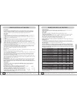
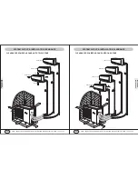
To drain the condensate easily, the drain hose should be inclined downward (pitched towards drain direction 
1/4" per foot).

Figures below from the 2nd to 5th show some incorrect practices.

Drain hose may be extended using the hose coming with the installation list.

STUFF AND SEAL THE HOLE FOR COPPER LINE SET/WIRE CABLE/DRAIN HOSE 

Use putty to seal the wall hole.

Use clamp (pipe fastener) to secure the 
pipe at specified position.

INSTALLATION-INDOOR UNIT

SHAPE THE DRAIN HOSE

REFIT DRAIN HOSE FROM THE RIGHT TO THE LEFT SIDE     

If drain hose needs to be refitted from the original 
position (right side) to left side of the indoor unit, 
careful handing is very necessary. 

Refitting method: remove the drain hose from 
original position, without breaking hose. Unplug 
the plug at the left side. Apply water-resistant glue 
to fit the drain hose and the fitting before securing 
it.

Apply water-resistant glue onto the plug and fit it 
back into the condensate connection at right side. 

NOTES: May use some sort of clamp to double secure connections.

Condensate connection

at left side

Drain hose

HANG INDOOR UNIT 

Run copper set/wire cables/drain hose through the 
wall hole and hang the indoor unit onto the 
mounting plate (place the hook on the mounting 
plate into the hanging rib at rear side of plastic 
casing).

Snap the plastic casing bottom into the mounting 
plate, gently .

Sealed with putty

Secure the piping/
wiring set with clamp

Trim the extra portion.

2 in or less
from floor

P27 OF 40

YMGI, Engineered Comfort Products for A Sustainable and Efficient Green World !

YMGI, Engineered Comfort Products for A Sustainable and Efficient Green World !

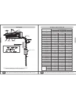
If pipes need to come out of the right side (facing 
the front of indoor unit) of the indoor unit, snap off 
portion

1

on plastic casing.

If pipes need to come out of the bottom side 
(facing the front of indoor unit) of the indoor unit, 
snap off portion

2

on plastic casing.

If pipes need to come out of the left side (facing 
the front of indoor unit) of the indoor unit, snap off 
portion

3

on plastic casing.

Hole Diameter: 2.5~3 In

Align ruler with straight line

Insert ruler

DRILL 3IN HOLE FOR PIPING/WIRING/DRAIN

Locate the centre where the hole will need to 
drilled.

Drill the holes of 2.5-3Inch diameter. A down pitch 
about 1/4" per foot, as illustrated below, is needed 
for the hole, in order to drain the condensate 
properly.

PREPARE INDOOR UNIT- COPPER LINE SET/DRAIN HOSE

1

2

3

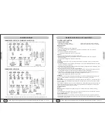
INSTALL DRAIN PIPE AT INDOOR

The drain hose must be placed beneath the copper 
pipes and MUST NOT be hunched or bended 
sharply.                                                 

Do not pull the drain hose too hard, otherwise it 
may get broken.

Before passing drain hose through the hold, wrap 
with insulation to keep from possible damage.

The copper pipe and the drain hose must be 
wrapped by piping wrap. 

Insulation pad (underlay) should be used where 
the pipe contacts the wall.

Slice the insulation before 
bending.     

Hold the 90 degree bend root, 
bend one tube one time, slowly, 
no quicker than 10 seconds/90 
degree bend.

If pipes need to come out of the rear side (facing 
the front of indoor unit) of the indoor unit, no need 
to snap off anything.

If pipes need to be rerouted to a different direction 
from the one preset at factory (towards left side, if 
facing the front cover of indoor unit), lay down the 
indoor unit on soft cushion or foam. Don't rub the 
plastic casing.

In order to keep from pipe damage, need to bend 
the copper tubing set gently and slowly (finish 
bending no less than 10 seconds/90 degree), by 
holding at the root of the original 90 degree bend 
nicely and firmly. Don't rub two copper lines during 
bending. Better to cut off the insulation and bend 
the two pipes one by one, not two together.

Drain hose coming with indoor unit

Drain hose extending to drain line

PREPARE INDOOR UNIT- COPPER LINE SET/DRAIN HOSE

INSTALLATION-INDOOR UNIT

Summary of Contents for WMMS-09EW-V2B

Page 1: ...pment NEC State City or Local Codes and related manuals from us Otherwise damage to equipment or property even injury to people may occur Installer Currently licensed HVAC installer only Read this man...

Page 2: ...ory labs third party labs and various fields applications following related industrial and company standards 7 Field installation details matter with all 1 if your units will work correctly and proper...

Page 3: ...ty approval because warranty is approved only to those qualified and successful installations by qualified HVAC technician I know the warranty if approved is a standard 5 year compressor and 1 year ot...

Page 4: ...eral knowledge and experience a full single head installation may normally cost anywhere from 800 to 1500 These costs are estimates and your actual costs may differ due to job nature and location 8 Nu...

Page 5: ...D MUST READ MUST READ P7 OF 40 P8 OF 40 YMGI Engineered Comfort Products for A Sustainable and Efficient Green World YMGI Engineered Comfort Products for A Sustainable and Efficient Green World The co...

Page 6: ...t Green World YMGI Engineered Comfort Products for A Sustainable and Efficient Green World If the damage is minor or partial that you choose to accept you can contact the distributor or YMGI to discus...

Page 7: ...he Customer Request to Ship Products to YMGI Service Center for Inspection and Repair and Authorization to Charge form 2 You will review the form and fill all fields appropriately sign and send back t...

Page 8: ...copper tube Aluminum fin copper tube Swing Motor Model MP28VB 1 4 3 8 MP28EC MP35XX Output of Swing Motor W 2 2 2 5 Fuse A PCB 3 15A Transformer 0 2A PCB 3 15A Transformer 0 2A PCB 3 15A Transformer 0...

Page 9: ...WS DIMENSIONS MOUNING BRACKET CLEARANCE YMGI Engineered Comfort Products for A Sustainable and Efficient Green World YMGI Engineered Comfort Products for A Sustainable and Efficient Green World WMMS 0...

Page 10: ...this mode only indoor fan is running at setting status Under auto fan speed it will run by cooling auto fan Heating Mode When the indoor receiving the information mode clash from outdoor unit and the...

Page 11: ...ter setting sleep procedure 1h T preset will increase 1 F 2h later T preset will O O increase 2 F then remain the temperature T preset will not exceed 86 F under heating after setting sleep O O proced...

Page 12: ...ER 4 OVER 80 CLEARANCE REQUIRED AROUND UNITS DUAL ZONE 2 YMGI Engineered Comfort Products for A Sustainable and Efficient Green World YMGI Engineered Comfort Products for A Sustainable and Efficient G...

Page 13: ...E REQUIRED AROUND UNITS QUAD ZONE OVER 2 OVER 4 OVER 4 OVER 80 YMGI Engineered Comfort Products for A Sustainable and Efficient Green World YMGI Engineered Comfort Products for A Sustainable and Effic...

Page 14: ...for screws Align mounting plate holes with those holes drilled on the wall and put anchors or screws into the holes to secure mounting plate Steps To Mount Plate a b c Drill mounting holes to make su...

Page 15: ...ipes need to come out of the bottom side facing the front of indoor unit of the indoor unit snap off portion 2 on plastic casing If pipes need to come out of the left side facing the front of indoor u...

Page 16: ...N INDOOR AND OUTDOOR UNITS Firstly connect copper tubes at indoor unit Bend pipes by tools but not by hands Extra length is needed for future service REFRIGERANT PIPES For distance other than 25 betwe...

Page 17: ...25 26 27 28 29 30 Jumping connector 1 32 Transformer 48X26P 1 33 Wire clamp 1 34 Rear clamp 1 35 Connecting cable 1 36 swing louver clamp 1 37 swing louver 1 38 swing louver up 1 39 swing louver down...

Page 18: ...e 68012019 1 Receiver board 30545042 1 Front panel 200022921 1 Guide louver 261120432 1 Guide louver 261120422 1 Motor MP28EC 15212002 1 Right motor clamp 26112429 1 Bearing holder 26152423 1 Motor FN...

Page 19: ...2 Front case 200026524 1 Front panel 2000284402 1 remote control YT1F 30510049 1 Displaying light board 22432071 1 Electric box cover 1 20112019 1 Wire clamp 71010103 1 Terminal board 4201026601 1 El...

Page 20: ...mfort Products for A Sustainable and Efficient Green World DISASSEMBLY PROCEDURE OPERATING PROCEDURES PHOTOS Disassemble Front Panel Lift the front panel upward Firstly screw off a screw fixing the up...

Page 21: ...ny damages to person or property of whatever kind direct or indirect special or consequential whether resulting from use or loss of use of the product The original licensed installer or current servic...

Reviews: