


INST
ALLER'S
INSTRUCTION
INST
ALLER'S
INSTRUCTION
P25 OF 40
P26 OF 40
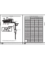
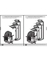
HEIGHT LIMITS OF INDOOR AND OUTDOOR UNITS
* Either the indoor unit or the outdoor unit can be higher, but the height difference must comply the stated r
equirements.
* Try to reduce the bending of the piping line as much as possible so as to avoid possible negative impacts upon
the performances of the units.
Indoor unit
Outdoor unit
Lift
* Make P-trap if elevation drop difference is more than 25", as illustrated below.
Indoor unit
Outdoor unit
Drop
P-Trap
18 In
Refrigerant Pipe Min/Max. Length, Rise and Drop Height
1,000 Btu/h
09-12
18-24
30-36
Max. Length (Ft.)
50
75
100
Max. Rise Height (Ft.)
20
25
35
Max. Drop Height (Ft.)
28
35
50
Min. Length (Ft.)
15
15
15
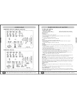
Locate the central hole at the stud (firn structure)
At least 12"
18" or more
from sidewall
Respect the slope
Plumb
Mounting Plate
Anchors of self-
tappping screw
18" or
more from
sidewall
Install Mounting Plate and Drill Hole for Combination of Copper Line/Wire Cable/Drain Hose
NOTES:
Anchors must be put into the holes, where the solid
arrows are pointing, as shown above, to secure the
mounting plate firmly and to hold the weight of indoor
unit. If more screws/anchors are to be used, make
sure to keep the two holes close to each other, at
least 2 inches apart.
Mounting plate should be attached to the structural
part of the wall. Minimum clearance, as shown below,
is required in order to ensure proper airflow and
enough service room.
INSTALLATION-INDOOR UNIT
INSTALL WALL MOUNT PLATE
* Check unit to make sure the unit is good shape and ready to install.
* Check to make sure the installation location is firm enough to hold the weight of the whole unit and is
convenient to installation, maintenance, service and close to the indoor unit but not causing noise or airflow
issues to neighbour.
* Install Indoor unit. Enough anchor bolts/nuts shall be used to secure mounting plates for indoor units.
Brackets should be at level position.
*
Mark drill positions. At least 4 anchor holes, one at each perimeter corner of the plate are needed to secure the
plate, where the bold arrows are pointing, as shown in the picture above. Refer to the specification sheet for
unit weight so that enough anchors are installed at proper positions.
* Pre-drill guiding holes where are marked for anchors or screws on the wall
* Confirm the position of the holes and finish drill to the depth needed for anchors (NOT for screws)
* Align mounting plate holes with those holes drilled on the wall and put anchors or screws into the holes to
secure mounting plate.
Steps To Mount Plate:
a
b
c
Drill mounting holes
to make sure at least
either one of three
dimensions a, b and
c is 16" center to
center.
YMGI, Engineered Comfort Products for A Sustainable and Efficient Green World !
YMGI, Engineered Comfort Products for A Sustainable and Efficient Green World !
INSTALLATION LOCATIONS & CAUTIONS
All Units Shall Be Installed by Licensed Contractor or Technician.
Read Manuals before Installation.
* The location and structure shall also be convenient for both installation and service.
* The location shall NOT be where discharge air and noise could bother your neighbor.
* The location shall NOT be somewhere drain may cause any damage to property or bother the neighbor.
* The location shall NOT be somewhere soldering or torching work may cause fire or smoke to the
materials around.
* The location shall NOT be somewhere near flammable gases.
* The location shall NOT be in or close to corrosive gases.
* The location shall NOT be somewhere children can access.
Check the unit for damage and missed parts or accessories. If damage is found or parts are found missing, call
the distributor right away.
Spin fan wheels or blades to check if and make sure they can rotate freely. If fan wheel scratches with housing,
call the distributor right away and do not to proceed with the installation before it is fixed.
Check the unit to make sure no foreign materials has been left in the unit.
Check all the parts and accessories that are needed other than those provided with the unit.
It is strongly recommended to only use YMGI supplied or recommended parts and accessories.
Be sure a properly sized circuit breaker is for the electric power to the units.
Pre-build the support platform on the ground or bracket for the wall before or during construction and before
installation. Refer to the table below for footprint dimensions.
Read installation instructions of all units thoroughly.
Ask rep./distributor/us anything you are not sure about.
Get your tools and parts ready for installation.
CAUTION & SUGGESTIONS TO FOLLOW PRIOR TO INSTALLATION
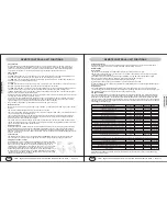
PIPING AND WIRING SIZES-UNITS MADE AFTER 05/2010
Unit
Connection Copper
Pipe Sizes
Min/Max.Length
+/- Elevation
Wires from Outdoor
to Indoor Unit
Mini. Wire Size
Outdoor-Indoor Units
Fuse Is Factory
Installed
09K
1/4+3/8"
15/30/30/15
N(1)/2/3/G
16AWG
At Indoor Control Board
12K
1/4+3/8"
15/30/30/15
N(1)/2/3/G
16AWG
At Indoor Control Board
18K
1/4+1/2"
15/30/30/15
N(1)/2/3/G
16AWG
At Indoor Control Board


