


32
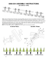
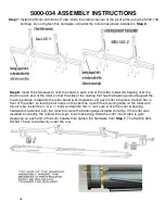
5000-034 ASSEMBLY INSTRUCTIONS
(JD 612FC & 712FC)
Step 1:
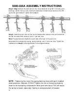
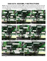
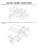
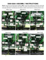
Attach the 5000-202 mount brackets to the frame between rows 4 & 5, 5 & 6, 7 & 8, and 8 & 9 using the 5/8 x 6 bolts,
mounting straps, & 5/8” lock hex nuts. Attach the 5000-263 mount brackets to the frame between rows 1 & 2, 2 & 3, 10 & 11,
and 11 & 12. The 5000-263 mounts between rows 1 & 2 and 2 & 3 will use 5/8 X 6 bolts, mounting straps, & 5/8” lock nuts. The
5000-263 mounts between rows 10 & 11 and 11 & 12 will each use 3) 5/8 X 6 bolts & 1) 5/8 X 6 Carriage bolts (1 used on the
top left of each mount on these rows), mounting straps, and 5/8” lock nuts. Slide the mount bracket up so the deck plate
adjustment rod is located in the cut out of the mount bracket.
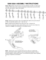
Note:
Do not fully tighten hardware until
Step
6 after all of the pivot arms & springs are installed.
6 Center Rows
Outside 3 Rows
Summary of Contents for 5000-025A
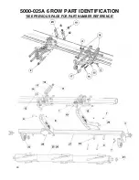
Page 39: ...39 5000 025A 6 ROW PART IDENTIFICATION SEE PREVIOUS PAGE FOR PART NUMBER REFERENCE ...
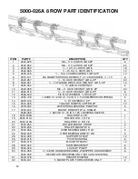
Page 41: ...41 5000 026A 8 ROW PART IDENTIFICATION SEE PREVIOUS PAGE FOR PART NUMBER REFERENCE ...
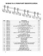
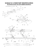
Page 43: ...43 5000 027A 12 ROW PART IDENTIFICATION SEE PREVIOUS PAGE FOR PART NUMBER REFERENCE ...
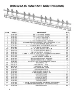
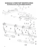
Page 45: ...45 5000 028A 16 ROW PART IDENTIFICATION SEE PREVIOUS PAGE FOR PART NUMBER REFERENCE ...
Page 49: ...49 ...
Page 50: ...50 ...
Page 52: ...52 2565 785_Rev_D 12 2018 ...