24
5000-027A ASSEMBLY INSTRUCTIONS
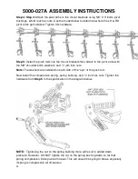
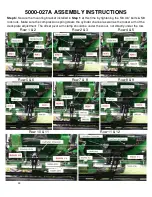
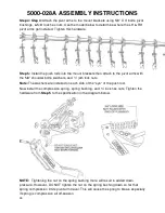
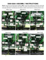
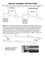
Step 6:
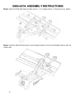
Secure the mounting bracket installed in
Step 1
at this time by tightening the 5/8 X 6” bolts & 5/8
lock nuts. Make sure the compression spring clears the cylinder channel as well as the rocker arm of the
deck plate adjustment. The offset pivot arm clamp should be under the snout, not directly under the row.
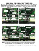
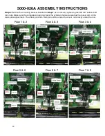
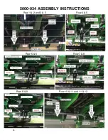
Row 1 & 2
Row 2 & 3
Row 4 & 5
Row 5 & 6
Row 7 & 8
Row 8 & 9
Row 10 & 11
Row 11 & 12
Summary of Contents for 5000-025A
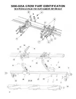
Page 39: ...39 5000 025A 6 ROW PART IDENTIFICATION SEE PREVIOUS PAGE FOR PART NUMBER REFERENCE ...
Page 41: ...41 5000 026A 8 ROW PART IDENTIFICATION SEE PREVIOUS PAGE FOR PART NUMBER REFERENCE ...
Page 43: ...43 5000 027A 12 ROW PART IDENTIFICATION SEE PREVIOUS PAGE FOR PART NUMBER REFERENCE ...
Page 45: ...45 5000 028A 16 ROW PART IDENTIFICATION SEE PREVIOUS PAGE FOR PART NUMBER REFERENCE ...
Page 49: ...49 ...
Page 50: ...50 ...
Page 52: ...52 2565 785_Rev_D 12 2018 ...


