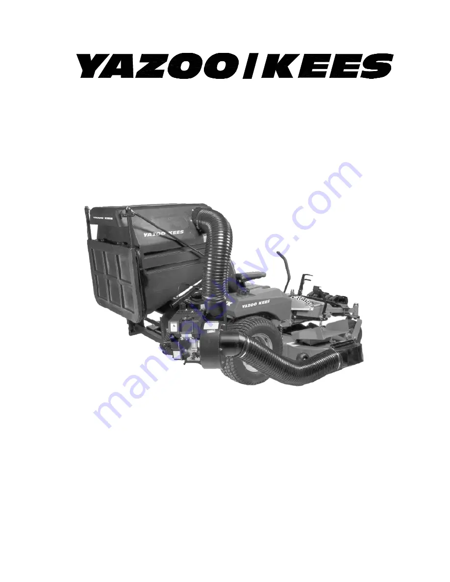
Operator’s Manual
Models: Z12A
Please read these instructions carefully and makesure you understand them before using the machine.
Z12 Commercial
Collection System
MANUAL NO. 200842 REV 02 (10/30/03)
Page 1: ...Operator s Manual Models Z12A Please read these instructions carefully and make sure you understand them before using the machine Z12 Commercial Collection System MANUAL NO 200842 REV 02 10 30 03...
Page 2: ...13 Maintenance and Service Instructions Transport 14 Cleaning and Washing 14 Storage 14 Preventative Maintenance Schedule 14 Engine Service and Maintenance 15 Caring for Vacuum Hoses 15 Cleaning Exhau...
Page 3: ...able Capacity 10 cu ft 8 4 bu or 0 29 m3 Hose 7 in 18 cm upper and lower Height 47 50 in 119 127 cm Length 38 in 97 cm Width without hose or blower 37 in 94 cm Width with hose and blower 49 in 124 cm...
Page 4: ...ght Bar Boot and Hitch may look different from those shown in this diagram Container Release Lever Hitch Bracket Upper Frame Upper Hose Vacuum Assembly Inlet Front Weight Front Weight Bar Boot Hitch D...
Page 5: ...d Hitch may look different from those shown in this diagram FEATURES CONTROLS Container Release Lever Inlet Arm Exhaust Hitch Bracket Upper Frame Hitch Lower Frame Front Weight Front Weight Bar Door H...
Page 6: ...gine to cool before refueling Do not smoke while fueling or operating equipment Never refuel or drain the machine indoors Check that operator s controls safety switches hoses and shields are securely...
Page 7: ...ng turns and crossing roads and sidewalks Stop vacuum and mower blades if not mowing Do not operate machine under the influence of alcohol or drugs Use care when loading or unloading the machine into...
Page 8: ...er Frame inside the Upper Frame 2 Align holes corresponding to desired position of frame 3 Secure with eight 8 1 2 x 1 1 4 hex bolts and eight 8 1 2 nylon lock nuts 1 Cut straps around carton and remo...
Page 9: ...hat carton 2 Slide the Z12 into the hitch 3 Line up holes in the Hitch and Z12 and secure with two 2 3 8 wire lock pins 4 Position the Hitch Brackets so that they are aligned with the holes on the top...
Page 10: ...3 8 x 2 1 2 hex bolts two 2 3 8 hex nuts and four 4 3 8 flat washers 6 Place the Inlet Cover on the Vacuum Assem bly with the inlet cylinder pointing downward and forward toward the mower deck 7 Secur...
Page 11: ...to clear the chute mounting bar and the discharge chute mounting tab on the deck 13 Reinstall the clamp at the front of the assembly so that the tab at the lower end of the clamp passes thru the rect...
Page 12: ...er 1 Slide one Hose Clamp over each end of the Upper Hose Slide one end of the hose over the Vacuum discharge opening and the other end over the Inlet Tighten the Hose Clamps to secure hose in place 2...
Page 13: ...ort coil from where the original cut was started 4 Use the utility knife to score the support coil between the beginning and end of the web cut Set aside the knife and finish breaking the coil by hand...
Page 14: ...ng the Vacuum 1 NEVER USE THE Z12 WITHOUT THE VACUUM INLET COVER AND ALL HOSES SECURELY ATTACHED 2 Make sure both hoses are connected at both ends Inspect hoses prior to each use 3 Do not use the Z12...
Page 15: ...in the container the mower must be backed up onto the trailer to avoid tipping Transport Cleaning and Washing Regular cleaning washing and lubricating will prolong the service of the machine NOTE Use...
Page 16: ...2 To prolong the life of the hose periodically rotate hose and turn hose end to end Refer to Preventative Maintenance Schedule in this manual 3 Avoid twists and sharp turns in the hoses as they will i...
Page 17: ...e hose and clean inlet 2 Container full 2 Inspect and empty 3 Engine not reaching full RPM 3 See Engine Runs Poorly above 4 Fan blades bent or broken 4 Replace repair impeller Unusual vibration 1 Soli...
Page 18: ...18 NOTE Your Front Weight Bar Boot and Hitch may look different from those shown in this diagram AUXILIARY ENGINE ASSEMBLY...
Page 19: ...19 NOTE Your Front Weight Bar and Hitch may look different from those shown in this diagram SPINDLE DRIVE ASSEMBLY...
Page 20: ...20 CONTAINER ASSEMBLY 1 2 3 4 5 6 7 8 9 10 11 12 13 14 15 16 17 18 19 20 21 22 23 24 4 11 12 18 8 12 18 12 25 26 27 28...
Page 21: ...0405 14 WASHER 1 4 13 200408 1 INLET 14 097076 1 HOSE CLAMP 15 200478 2 LATCH 16 200641 6 SCREW 10 24 X 1 1 4 P T H 17 000134 2 BOLT 1 4 20 X 2 18 108134 1 DOOR SEAL KIT CONTAINS 3 SEALS 19 099072 6 N...
Page 22: ...22 FRAME ASSEMBLY 1 2 3 4 5 6 7 8 9 10 11 12 13 14 15 16 17 18 19 20 21 22 23 24 11 7 6...
Page 23: ...2 2 NUT 1 4 20 NYLOC 9 000405 4 WASHER 1 4 10 000425 1 WASHER 1 2 11 003585 2 COTTER PIN 3 32 X 3 4 12 000423 1 LATCH BASE 13 200708 1 LATCHCATCH 14 099008 2 BOLT 1 4 20 X 1 15 000382 1 CLEVIS PIN 3 1...
Page 24: ...24 POWER UNIT ASSEMBLY 1 2 3 4 5 6 7 8 9 10 11 12 13 14 15 16 17 18 19 20 21 22 23 5 6 4 4...
Page 25: ...BOLT 3 8 16 X 2 1 2 10 000415 4 WASHER 3 8 11 099065 2 NUT 3 8 16 NYLOC 12 099079 4 NUT 5 16 18 NYLOC 13 062092 1 ENGINE MOUNT 14 200671 1 BOOT MAX II 200818 1 BOOT ZT MAX 15 093814 1 HINGE PIN 5 16...
Page 26: ...26 HITCH ASSEMBLY Quantity 3 for Spindle Drive Units Quantity 4 for Auxiliary Engine Units 1 2 3 4 5 6 7 8 9 10 11 12 13 14 15 14 13 14 14 10 14 14 10...
Page 27: ...C 4 099031 4 BOLT 1 2 13 X 1 1 2 5 092731 1 FRONT WEIGHT HOLD BAR 6 099668 2 CLEVIS PIN 3 8 X 1 7 099616 2 HAIR PIN 11 8 099113 4 BOLT 3 8 16 X 3 1 2 9 092519 2 FRONT WEIGHT CLAMP 10 099065 8 NUT 3 8...
Page 28: ...28 SPINDLE DRIVE ASSEMBLY 1 2 3 4 5 6 7 8 9 10 11 12 13 14 15 16 17 18 19 20 21 22 23 24 25 26 27 28 29 30 31 32 33 34 35 36 37 39 40 41 42 43 44 45 23 27 21 28 28 29 27 15 8 29 28 14 38 46 46...
Page 29: ...00472 3 RHSNB 5 16 X 1 25 21 539 990184 13 NUT 5 16 CTR LOCK 22 539 990717 3 NUT 5 16 NYLOC 23 539 990799 8 RHSNB 5 16 X 625 SHORT NECK 24 539 990208 1 RHSNB 5 16 X 1 00 25 539 990362 2 SCREW 1 4 X 62...
Page 30: ...39 106725 1 BELT 52 539 106726 1 BELT 61 6 539 106744 1 STACKED SHEAVE 42 48 539 106745 1 STACKED SHEAVE 52 539 106746 1 STACKED SHEAVE 61 7 539 108946 1 DOUBLE HEX STACKED SHEAVE 42 48 539 108947 1 D...
Page 31: ...31...
Page 32: ...chnical assistance please contact your local dealer or Yazoo Kees Customer Service Yazoo Kees Power Equipment 700 Park St Beatrice NE 68310 PHONE 402 223 2391 TOLL FREE PHONE 877 368 TURF FAX 402 223...