


13
EN
O R I G I N A L I N S T R U C T I O N S
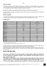
PRODUCT OPERATION
Preparing for operation
Unpack the product by removing all packaging components.
Check that the on/o
ff
switch is in the o
ff
position – O.
In case of selecting the battery, set the power switch to the OFF position.
Select the type of in
fl
ated item. The compressor allows for in
fl
ating products requiring large volumes of air, e.g. mattresses, beach
balls, etc., or in
fl
ating products requiring high pressure, e.g. tyres, balls, etc. For both modes, other hoses and corresponding tips
are used.
When selecting the large-volume mode connect the hose to the socket at the back of the housing (II). The hose is provided with
cut-outs through which the socket pins must
fi
t, and then the hose must be turned to lock its position in the socket.
If high-pressure mode is selected, the hose is permanently mounted to the compressor and only needs to be unwound from the
handle at the back of the housing. The selected work tip can be installed in the hose valve. Set the valve lever so that it is parallel
to the valve and then insert the tip into the valve (III), then lower the valve lever to lock the tip in the valve (III).
Select the power supply source: battery or vehicle’s 12 V system.
Slide the battery into the battery socket guides until it snaps into the socket (IV).
If the vehicle’s 12 V system is selected as the power supply source, set the power switch in the position marked with a light symbol.
Unwind the power cord completely and plug the plug into the vehicle’s system socket, the so-called cigarette lighter socket.
Connect the selected hose to the in
fl
ated product.
The compressor is ready for use.
Turning on and o
ff
The device is turned on by means of the on/o
ff
switch. The on/o
ff
switch has three positions. The middle one indicates that it is
in the o
ff
state – O.
Setting the on/o
ff
switch to the – I position means operation in high-pressure mode.
Setting the on/o
ff
switch to the – II position means operation in the large-volume mode.
Using the device
The device has a display and a control panel in the form of buttons. The button marked PSI/BAR/kPa is used to select the unit of
pressure visible on the display. Each subsequent pressing of the button changes the pressure unit in the following sequence: PSI
(pound/square foot); bars and kilopascals.
The buttons marked with the “+” and “-” symbols are used to change the pressure value in the selected unit. The button marked
with “+” is used to increase the value, and the button marked with “-” is used to decrease the value.
The buttons allow for setting an automatic in
fl
ation end after setting the relevant pressure. Such manner of operation is only
available in the high-pressure mode. In the large-volume mode you cannot automatically end the in
fl
ating after reaching the set
pressure.
Set the desired pressure using the buttons. Approximately 3 seconds after the last button is pressed, the set value will start to
fl
ash
on the display and then the display will start to show 0.
During in
fl
ating, the display will show the current pressure and once the set value has been reached, the in
fl
ating will stop auto-
matically.
The compressor can also be used to pump air out of previously in
fl
ated products faster. This function is only available in large-vol-
ume mode. The hose used for in
fl
ating in this mode must be connected to the air inlet and then to the product from which the air
is to be pumped out. Start the compressor in the large-volume operating mode and wait for the air to be pumped out from the
product.
Warning! The compressor cannot be used as a vacuum pump.
When powered from the battery, setting the power switch to the light symbol will turn on a small
fl
ashlight built into the side of the
housing.
Safety instructions for battery charging
Caution! Before starting charging, make sure that the power unit body, cord and plug are not cracked or damaged. It is forbidden to
use a defective or damaged charging station and power unit! Use only the supplied charging station and power unit to charge the
batteries. The use of another power unit may result in
fi
re or damage to the tool. The battery should only be charged in a closed,
dry room, protected against unauthorised access, especially by children. Do not use the charging station and power unit without
the constant supervision of an adult! If you need to leave the room where the tool is being charged, disconnect the charger from
the mains by removing the power unit plug from the mains socket. If smoke, suspicious odours, etc. are escaping from the charger,
remove the charger plug from the mains socket immediately!
The compressor is supplied with an uncharged battery and should therefore be charged according to the procedure described
below with the included power unit and charging station before use. Li-ion (lithium-ion) batteries do not have the so-called “mem-
ory e
ff
ect”, which means they can be recharged at any time. However, it is recommended to discharge the battery during normal
Summary of Contents for YT-23247
Page 21: ...21 RU 5O C 40O C 80 7 0 7...
Page 22: ...22 RU O OFF II III III 12 IV 12 O I II PSI BAR kPa PSI 3 0...
Page 23: ...23 RU Li Ion 500 0 30 50 70 II V...
Page 24: ...24 RU 0 3...
Page 26: ...26 UA 5 O C 40 O C 80 7 0 7...
Page 27: ...27 UA O OFF II III III 12 IV 12 I II PSI BAR kPa PSI 3 0...
Page 28: ...28 UA 500 0 30 50 70 II V...
Page 29: ...29 UA 0 3...
Page 74: ...74 GR 5 O C 40 O C 80 7 bar 0 7 MPa...
Page 75: ...75 GR OFF II III III 12 V IV 12 V O II PSI BAR kPa PSI bars kilopascals 3 0...
Page 76: ...76 GR Li Ion 500 0 30 50 70 LED LED V LED LED LED LED...
Page 77: ...77 GR 0 3 Mpa...
Page 79: ...79 BG 5 O C 40 O C 80 7 bar 0 7 MPa...
Page 80: ...80 BG OFF II III III 12 V IV 12 V I II PSI BAR kPa PSI 3 0...
Page 81: ...81 BG Li Ion 500 0 30 50 70 II V...
Page 82: ...82 BG 0 3 MPa...


