


4 Specifications and External Dimensions for
Σ
-V-SD Drivers
4.2.1 Specifications
4-6
4.2
SERVOPACK
4.2.1
Specifications
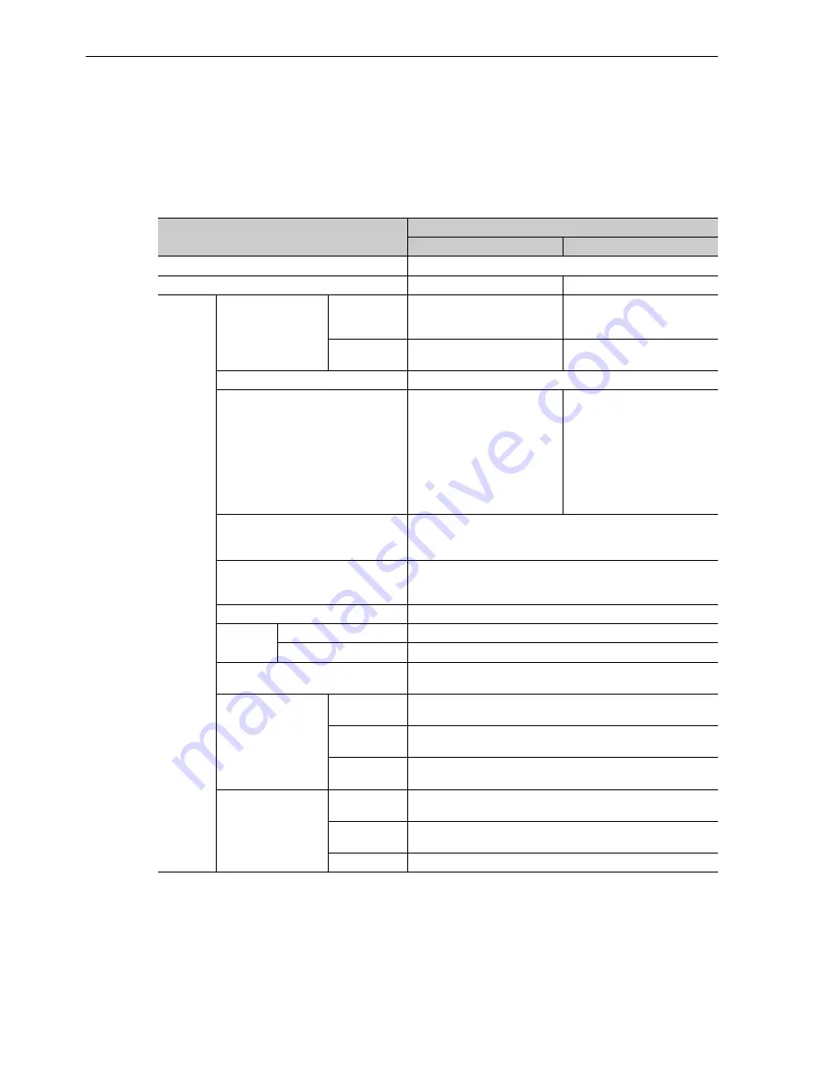
(1) Basic Specifications
Item
Specifications
For Spindle Motor
For Servomotor
Control Method
Sine-wave current drive with PWM control of IGBT
Applicable Motors Model
UAK
J
SGMGV
Functions
Feedback
Motor
Pulse encoder (phases A, B, and
Z), serial encoder: 17 bits
Serial encoder (absolute),
Standard type: 20 bits,
4-Mbps communications
Fully-closed
Loop Control
–
Serial conversion unit,
4-Mbps communications
Indications
CHARGE (orange), RDY (green), and ALM (red)
Dynamic Brake (DB) Functions
–
Built into some models
*1
or
provided externally by the user.
It operates when an alarm
occurs, when the main circuit
power supply turns OFF, when
the servo turns OFF, or when
the control power turns OFF.
The servomotor coasts to a stop
after the dynamic brake.
Fuses
Main circuit power: Not available (built into power regeneration
converter)
Control power: Built in
Protective Functions
Overcurrent, overload, main circuit voltage error, heat sink over-
heating, overspeed, encoder error, CPU error, PG disconnection
detected, parameter error, etc.
Compensation Functions
Quadrant projection compensation and predictive control
Control
Position Loop
Proportional control
Speed loop
Integral-proportional control and torque control
Fully-closed Loop Control
Standard feature (A motor encoder-external encoder branch con-
version unit is required.)
Analog Monitor
(Built-in)
*2
Number of
Channels
2 for each axis
Output Power
Range
±
10 V (linear range:
±
8 V)
Response
Frequency
1 kHz
USB
Communications
Connected
Device
Personal computer (application: SigmaWin for
Σ
-V-SD (MT)
compatible)
Communica-
tion Standard
USB 1.1 compliant, 12 Mbps (full speed support)
Functions
Status displays, parameter setting, and adjustment function
∗
1.
Dynamic brakes are built into the following models:
• SERVOPACKs for one axis: CACR-JU028A, CACR-JU036A, CACR-JU014D, and CACR-JU018D
• SERVOPACKs for two axes: CACR-JUM23
, CACR-JUM24
, and CACR-JUM25
If you use any other model, provide your own dynamic brake circuit.
The dynamic brake on the CACR-JU036A or CACR-JU018D does not operate when the control power supply is
turned OFF.
∗
2.
Do not use an analog monitor signal for system control. Use an analog monitor signal only for adjusting the motor
or obtaining data for maintenance purpose.