background image

1

Icon

Via icons on the desktop you gain direct access to the application related to the

icon.

2

Desktop

The desktop is the screen that is shown after login to Windows 

Ò

. It contains e.g.

links to the mostly used applications res. system components.

3

Task bar

The task bar is part of the desktop. When opening an application, a document or

a window, every running object is displayed as button on the task bar. Via this

buttons you can easily change between the open windows.

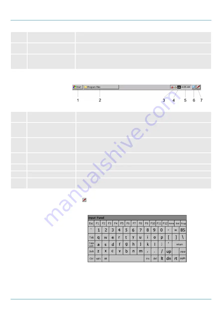
Basically the taskbar has the following structure:

1

Start button

This button offers you access to all components of your smartPanel such as

applications, system settings, file browser etc.

2

Open applications

For every open application a button can be found in the task bar. There is no

button for minimizing. The switch between the applications is performed via this

buttons.

3

Network connection

As soon as your smartPanel is connected via Ethernet you can see here the

Ethernet address. If there is no connection via Ethernet, the symbol is displayed

crossed out.

4

Keyboard layout

If you’ve connected a keyboard you can choose the requested language layout

via this button.

5

Time

This area shows the time that you can change via double click.

6

Show desktop

All windows are minimized and the desktop is shown.

7

Software keyboard

This button displays a keyboard at the screen. "Hide Input Panel" hides the key-

board again.

The button   allows you to select one of the available software keyboards. At the

moment the following standard keyboards are implemented:

At pushed Shift key:

Task bar

Software keyboard

Large Keyboard

VIPA HMI

Deployment

Operating system Windows Embedded Compact 7 > Structure

HB160 | TP-smart | H71-71A41-0 | en | 20-20


27

Summary of Contents for TP 307-SM

Page 1: ...TP smart H71 71A41 0 Manual HB160 TP smart H71 71A41 0 en 20 20 VIPA HMI smartPanel TP307 SM ...

Page 2: ...H71 71A41 0_000_TP307 SM 3 EN 2020 YASKAWA Europe GmbH Ohmstraße 4 91074 Herzogenaurach Tel 49 9132 744 0 Fax 49 9132 744 186 Email info yaskawa eu com Internet www yaskawa eu com ...

Page 3: ...on to a PLC system 24 3 4 Operating system Windows Embedded Compact 7 25 3 4 1 General 25 3 4 2 Structure 26 3 5 Integrated server 29 3 5 1 General 29 3 5 2 ftp server 29 3 5 3 Telnet server 30 3 5 4 VNC server 32 3 5 5 Web server 33 3 6 Access to the network resources 34 4 Installation Guidelines 36 4 1 Basic rules for the EMC equitable assembly of installations 36 4 2 EMC equitable assembly 39 4...

Page 4: ...criptions may be included for units which are not present at the customer site The exact scope of delivery is described in the respective purchase contract Hereby YASKAWA Europe GmbH declares that the products and systems are in compli ance with the essential requirements and other relevant provisions Conformity is indi cated by the CE marking affixed to the product For more information regarding ...

Page 5: ...1 71A410 0 It contains a description of the structure project engineering and deployment Product Order number as of state HW FW OS TP 307 SM H71 71A410 0 01 V1 0 2 WindowsÒ Embedded Compact 7 The manual is targeted at users who have a background in automation technology The manual consists of chapters Every chapter provides a self contained description of a specific topic The following guides are ...

Page 6: ...nnel in the n project design department n installation department n commissioning n operation CAUTION The following conditions must be met before using or commis sioning the components described in this manual Hardware modifications to the process control system should only be carried out when the system has been disconnected from power Installation and hardware modifications only by properly trai...

Page 7: ... that have been damaged by electrostatic discharges can fail after a temperature change mechanical shock or changes in the electrical load Only the consequent implementation of protection devices and meticulous attention to the applicable rules and regulations for handling the respective equipment can prevent failures of electrostatic sensitive modules Modules must be shipped in the original packi...

Page 8: ...able for monitoring and controlling of process cycles n WindowsÒ Embedded Compact 7 n Movicon 11 CE Standard 4096 I O Bytes n Processor ARM Cortex A8 1GHz n Flash memory 4GB RAM 512MB DDR n RS232 RS422 RS485 USB A and Ethernet interface n Robust plastic case n Display resolution 480 x 800 800 x 480 64K colors n Clock back up Goldcap n Resistive analog touch screen n Easy mounting via mounting clip...

Page 9: ...itive area Touch Screen 1 USB A interface USB 2 0 2 RJ45 jack for Ethernet communication LAN 3 RS232 RS422 RS485 interface COM 4 Slot for DC 24V voltage supply Front view Bottom view VIPA HMI Hardware description Structure Overview HB160 TP smart H71 71A41 0 en 20 20 9 ...

Page 10: ...yellow Description on off no link blinks on 100Mbit s link blinks off 10Mbit s link 9 pin SubD plug n Interface is compatible to the COM interface of a PC n Logical signals as voltage levels n Point to point links with serial full duplex transfer in two wire technology up to 15m distance n Data transfer rate up to 115 2kbit s Host USB A Ethernet connection RS232 interface VIPA HMI Hardware descrip...

Page 11: ...stems are available for the smartPanel n 512MB work memory RAM n 4GB user memory Flash n USB storage media using Host USB A interface Every Touch Panel has a work memory with a size of 512MB The work memory is not buffered and is deleted after shut down Please regard that also registry entries are stored in the work memory that are set back to default settings after the next re boot As internal pe...

Page 12: ...B 176 x 136 mm The degrees of protection are only guaranteed when the following is observed Material thickness at the mounting cut out 1 5 6mm The deviation from the plane for the panel cut out is 0 5mm This condition must be fulfilled for the mounted HMI device Permissible surface roughness in the area of the seal 120µm fric tion coefficient 120 USB storage media USB 2 0 Installation dimensions V...

Page 13: ...ation voltage to reference earth Inputs outputs AC DC 50V test voltage AC 500V Protective measures against short circuit Environmental conditions to EN 61131 2 Climatic Storage transport EN 60068 2 14 20 70 C Operation Horizontal installation EN 61131 2 0 40 C Vertical installation EN 61131 2 0 50 C Air humidity EN 60068 2 30 RH1 without condensation rel humidity 5 85 Pollution EN 61131 2 Degree o...

Page 14: ...pulses with Surge an appropriate external protective circuit with lightning protection elements like conductors for lightning and overvoltage is necessary 2 6 Technical data Order no H71 71A41 0 Type smartPanel TP307 SM Display Display size diagonal 7 Display size width 155 mm Display size height 88 mm Resolution 480 x 800 800 x 480 Aspect ratio 16 9 Type of display TFT color 64K colors MTBF Backl...

Page 15: ...S232 RS422 RS485 COM1 connector Sub D 9 pin male Serial COM2 COM2 connector Number of USB A interfaces 1 USB A connector USB A host Number of USB B interfaces USB B connector Number of ethernet interfaces 1 Ethernet Ethernet 10 100 MBit Ethernet connector RJ45 Integrated ethernet switch Video connectors Audio connections Technical data power supply Power supply rated value DC 24 V Power supply per...

Page 16: ...e Type 2 4X Protection class NEMA back side Dimensions Front panel 187 mm x 147 mm x 5 mm Rear panel 172 mm x 133 mm x 29 mm Installation cut out Width 176 mm Height 136 mm Minimum 1 5 mm Maximum front panel thickness 6 mm Net weight 500 g Weight including accessories 631 g Gross weight 900 g Environmental conditions Operating temperature 0 C to 50 C Storage temperature 20 C to 70 C Certifications...

Page 17: ...smartPanel into the openings The screws should point in the direction of the front panel 3 Screw the screws from the other side with the crosstip screwdriver 5 n For the cabling of the DC 24V power supply 18 32 VDC a black plug is included The connector is a plug with screw contacts The associated label is located on the back of the smartPanel n The smartPanel must always be grounded to earth Grou...

Page 18: ...t during operation the device must not be laid open to direct sun light After opening the control cabinet or desk there are parts with pos sible dangerous voltage available For all signal connections only screened cables are permitted Signal cables must not be let within the same cable shaft as high voltage cables VIPA HMI Deployment Commissioning HB160 TP smart H71 71A41 0 en 20 20 18 ...

Page 19: ... otherwise no update is executed 1 Go to www vipa com 2 Click on Service Support è Downloads è Firmware 3 Via HMI navigate to your smartPanel download the ZIP file for the update process and unzip the content in the root directory of the USB stick 1 Connect the smartPanel to the power supply ð The smartPanel starts with the Startup Manager 2 There is a button on the initial screen with a counter w...

Page 20: ...ort of the smartPanel ð The update process starts automatically and can take several minutes After successful update the message Process completed successfully appears A log file lastupdate log is generated and saved in the root directory of the USB stick 2 Remove the USB Stick and reboot the smartPanel Transfer firmware from USB stick into smartPanel VIPA HMI Deployment Commissioning Firmware upd...

Page 21: ...er Change Settings you can set a password for the Startup Manager The password will be requested when interrupting the start countdown or before closing the Startup Managers by Exit By default no password is defined n In Control Panel Open the system settings like brightness of the display can be preset or the display can be re calibrated Here the MPI DP slave interface may also be configured Furt...

Page 22: ...a delay time 0 by using the buttons and 5 seconds are default n Via Rotation the orientation of the panel can be changed Via Program start with you can add programmes which have to start automatically 1 Select start and assign a name for the program 2 Upload your program with VIPA HMI Deployment Commissioning Startup Manager HB160 TP smart H71 71A41 0 en 20 20 22 ...

Page 23: ...registry settings for the back light the local settings and the LAN settings will be saved by Backup in Flashdisk è Backup The name of the backup file is backup bkv Which settings will be saved and the storage location are defined in the file ToDoList xml under Flashdisk è VipaStartup These can be adjusted accordingly The Startup Manager will be closed by Exit and the system returns to the Windows...

Page 24: ...n time version of the HMI SCADA project engineering platforms your project is run able n By using the according communication driver the smartPanel supports connecting options to the PLC via field bus and Ethernet n During operation your operating device communicates with the according PLC and reacts to the application courses in the PLC according to the configured processes Via dialogues configur...

Page 25: ...on an object and then dragging you can move the object on the screen If no object is selected a frame is created by the dragging that selects the touched objects The windows can be moved via the head bar Here you can also find the OK button to confirm entries and the X button for exiting the dialog You can not exit WEC7 By switching the power supply off and on again you can restart WEC7 Before a r...

Page 26: ...anel reboots Please use the Store tool via Start è Programs è Tools è System Tools Store for manual storage 3 4 2 Structure VIPA HMI Deployment Operating system Windows Embedded Compact 7 Structure HB160 TP smart H71 71A41 0 en 20 20 26 ...

Page 27: ... is no button for minimizing The switch between the applications is performed via this buttons 3 Network connection As soon as your smartPanel is connected via Ethernet you can see here the Ethernet address If there is no connection via Ethernet the symbol is displayed crossed out 4 Keyboard layout If you ve connected a keyboard you can choose the requested language layout via this button 5 Time T...

Page 28: ...erties opens Here you can change the settings for the monitor options n Set Ethernet Parameters The dialog field for pre setting an Ethernet address can be found in Start è Settings è Network and Dial up Connections The default setting is address assignment via DHCP n System Properties System Via Start è Settings è Control Panel è System you receive information about the version of the current Win...

Page 29: ...tion that waits for the contact request of a client application and exchanges messages with it after contact start This communication type is called Client Server communication Computer within a network where at least one server is running Data transfer Server Client Data transfer Client Server 3 5 2 ftp server By means of a ftp server data between client and server can be exchanged Here you can c...

Page 30: ...monitor the IP address data via in the taskbar 4 After you ve confirmed the pre settings start your ftp client e g Windows Explorer and enter the following text into the address bar ftp wince vipatp IP Adresse ð In the appearing explorer window you can execute the requested file opera tions 3 5 3 Telnet server Telnet is a text based client server protocol on TCP level Using of a Telnet client like...

Page 31: ...ipatp entry is hidden ð After entering valid user data a command line for entries appears By entering Exit res closing the window you can terminate the Telnet connection at any time After establishment of a Telnet connection the smartPanel provides you with commands A list of possible commands with a short description is available via the command help By beginning with help before a command you re...

Page 32: ... deactivate all safety attitudes with the VNC server you should use these exclusively for start up For this reason the VNC server is on delivery deactivated Due to software reasons YASKAWA does not support the VNC server function The VNC connection establishment has the following approach 1 Start the VNC server via Start è Programs è Tools è winvnc or activate the VNC server in the Startup Manager...

Page 33: ...f the smartPanel res of websites in the smartPanel The administrative access to the http server happens via Ethernet from the PC by setting the IP address of the smartPanel with attached Admin type Using the websites you may e g publish online documentations for a connected PC or go online with applications on the PC As web admin you have access to all functions that are required for uploading and...

Page 34: ...can be listed by the command net view PC Name n For example net view testserver lists all shared resources of the network PC test server To test the physical connection a PING to the IP address of the network PC may be executed if there are problems while contacting the network PC The connection of a local name at the smartPanel with a shared drive of the network PC happens with the following appr...

Page 35: ...pped to network printer The printer may now be accessed as network printer For example you can print the content of the current directory using dir network printer The listing command for all network connections of your smartPanel is net use You can terminate already assigned network resources via net use local_name d Example net use data d deletes the network connection to the drive archive of te...

Page 36: ...nt ways n Electromagnetic fields RF coupling n Magnetic fields with power frequency n Bus system n Power supply n Protected earth conductor Depending on the spreading medium lead bound or lead free and the distance to the interference cause interferences to your control occur by means of different coupling mechanisms There are n galvanic coupling n capacitive coupling n inductive coupling n radian...

Page 37: ...e n Sparking lines sparking plugs collector of electric motors welding devices In the most times it is enough to take care of some elementary rules to guarantee the EMC Please regard the following basic rules when installing your PLC n Take care of a correct area wide grounding of the inactive metal parts when installing your components Install a central connection between the ground and the prote...

Page 38: ...cial EMC actions Consider to wire all inductivities with erase links Please consider luminescent lamps can influence signal lines n Create a homogeneous reference potential and ground all electrical operating sup plies when possible Please take care for the targeted employment of the grounding actions The grounding of the PLC serves for protection and functionality activity Connect installation pa...

Page 39: ...e even in case of an error Thus you have to connect the ground with the protected earth conductor To avoid ground loops local distant ground constructions cubicles construction and machine parts have to be connected with the protected earth conductor system in star topology Please regard at grounding n Connect the inactive metal parts as carefully as the active ones n Take care of impedance low me...

Page 40: ...oups Group A Group B Group C Group D Group A 1 2 3 4 Group B 2 1 3 4 Group C 3 3 1 4 Group D 4 4 4 1 1 The lines may be installed in common bundles or cable trusses 2 The lines have to be installed in different bundles or cable trusses without min distance 3 The lines have to be installed in different bundles or cable trusses inside of cubicles and outside of the cubicle but inside the building in...

Page 41: ...f the equipotential bonding conductor must not exceed 10 of the impedance of the screen where screened signal lines are connected between the dif ferent sections of the plant and the screening is connected to ground neutral on both sides n The cross sectional area of the equipotential bonding conductor must be calculated to carry the maximum equalization current The following cross sections have b...

Page 42: ...cover Do not connect the screen to PIN 1 of the connector In case of stationary operations it is recommended that the remove the insulation from the screened cable without cutting the screen and to attach this point to the screening neutral rail Potential differences can give rise to an equalization current via the screen connected between the two ground connections In this case you must install a...

Page 43: ...diode using a varistor using RC network Every cubicle must be provided with a power outlet for the PU These outlets must be wired to the distribution system which is also used to connect the neutral conductor for the cubicle The cubicle illumination should consist of incandescent lights e g LINESTRA lamps Avoid using fluorescent lamps as these lamps can cause interference If you can not avoid usin...

Page 44: ...en grounded by means of grounding straps connected to the body of the cubicle Cable routing Cabling divided into groups Power cables 230 400V and signal lines installed in separate channels or bunches Potential compensating When installing the equipment at separate locations check the installation of the potential compensating line Cable screen All covers of plugs are metallic All analog and data ...

Page 45: ...Appendix VIPA HMI Appendix HB160 TP smart H71 71A41 0 en 20 20 45 ...

Page 46: ...Content A History of changes 47 VIPA HMI Appendix HB160 TP smart H71 71A41 0 en 20 20 46 ...

Page 47: ...reated 18 35 n The orientation of the panel via Autostart Rotation was added to the description of the Startup Manager n The description Soft Reset was expanded 20 20 CI adjustment was done VIPA HMI History of changes HB160 TP smart H71 71A41 0 en 20 20 47 ...

Reviews: