YASKAWA SI-EL3/V Installation Manual Download Page 28

9  Fault Diagnosis and Possible Solutions

EN 28 

YASKAWA Europe 

YEU TOEP C710606 87A - V1000 Option Powerlink - Installation Manual
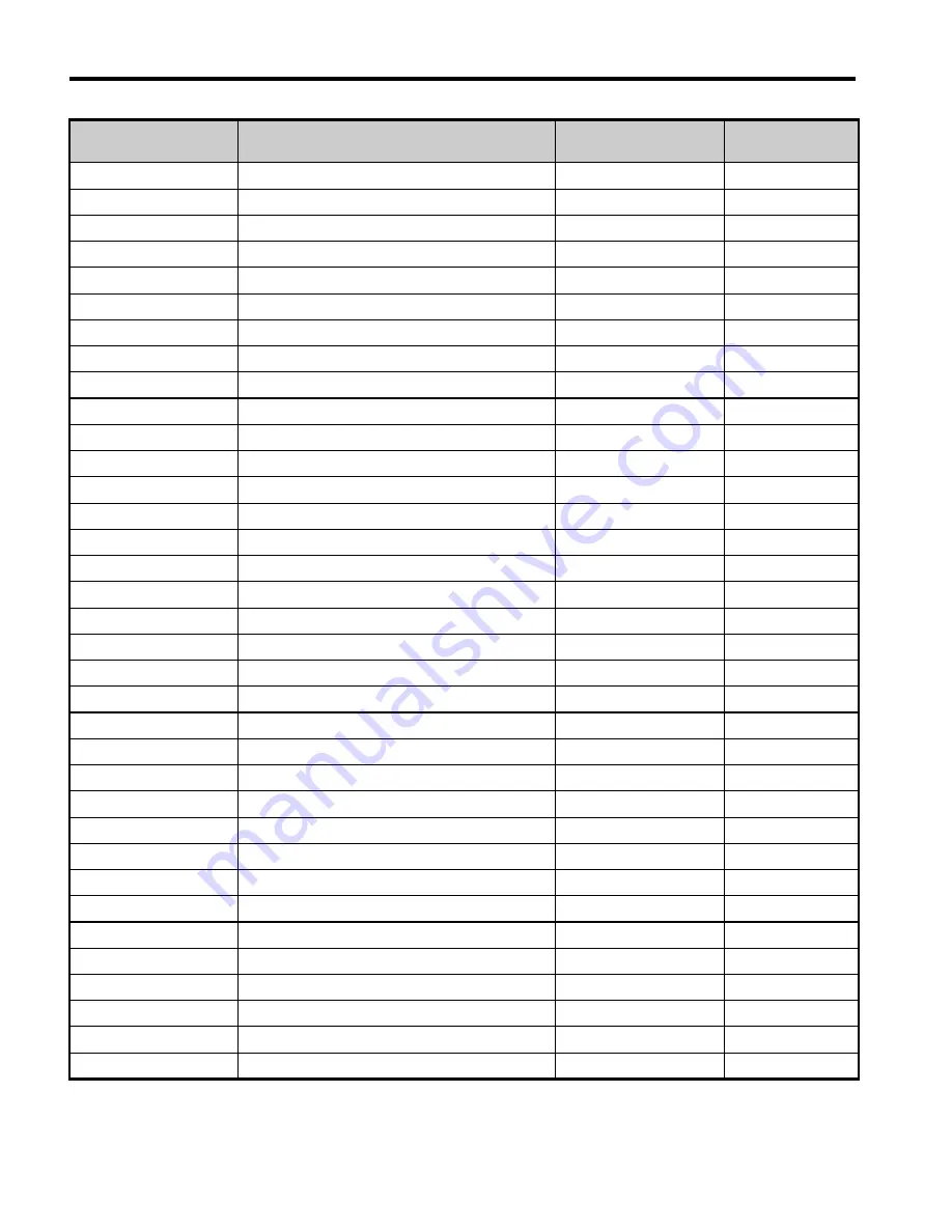
2310

Motor overload

oL1

0x0B

2221

Drive overload

oL2

0x0C

2311

Overtorque detection 1

oL3

0x0D

2312

Overtorque detection 2

oL4

0x0E

5420

Braking transistor fault

rr

0x0F

4410

Internal braking resistor overheat

rH

0x10

5441

External fault 3

EF3

0x11

5442

External fault 4

EF4

0x12

5443

External fault 5

EF5

0x13

5444

External fault 6

EF6

0x14

FF17

Cooling FAN fault

FAn

0x17

7180

Motor over speed (control mode using PG)

oS

0x18

8321

Speed deviation (control mode using PG)

dEv

0x19

7305

PG fault (control mode using PG)

PGo

0x1A

3130

Input phase loss

PF

0x1B

3300

Output phase loss

LF

0x1C

FF01

Motor overheat alarm

oH3

0x1D

5300

Digital operator disconnected

oPr

0x1E

5530

EEPROM error

Err

0x1F

FF08

MEMOBUS/Modbus Error

CE

0x21

FF07

BUS error

bUS

0x22

FF06

Control fault

CF

0x25

5481

Fault input from option card

EF0

0x27

FF02

PID feedback lost

FbL

0x28

FF03

Undertorque detected 1

UL3

0x29

FF04

Undertorque detected 2

UL4

0x2A

FF05

High slip braking OL

oL7

0x2B

FF31

Intermediary voltage fault

VCF

0x31

FF36

Output current imbalance

LF2

0x36

FF3B

Too many speed search restarts

SEr

0x3B

FF41

PID feedback loss

FbH

0x41

FF0D

External fault at input terminal S1

EF1

0x42

FF0E

External fault at input terminal S2

EF2

0x43

FF44

Mechanical weakening detection 1

oL5

0x44

FF45

Mechanical weakening detection 2

UL5

0x45

Error Code (Hex)

Meaning

Drive Display

INVR:0x0080 

Enum Value

Summary of Contents for SI-EL3/V

Page 1: ...oduct read this manual thoroughly and retain for easy reference inspection and maintenance Ensure the end user receives this manual 1 2 3 4 5 6 7 8 ATTENTION This product can only be used on V1000 dri...

Page 2: ...rior written permission of YASKAWA No patent liability is assumed with respect to the use of the information contained herein Moreover because YASKAWA is constantly striving to improve its high qualit...

Page 3: ...V1000 Option Table of Contents 1 Preface and Safety 4 2 Product Overview 8 3 Receiving 9 4 Powerlink Option Components 10 5 Installation Procedure 13 6 Powerlink Option Related Drive Parameters 20 7...

Page 4: ...e use and operation of that part Any warnings provided by YASKAWA must be promptly provided to the end user YASKAWA offers an express warranty only as to the quality of its products in conforming to s...

Page 5: ...ontact a YASKAWA representative Powerlink Option YASKAWA AC Drive SI EL3 V Powerlink option card Powerlink Standard for CANopen over Ethernet according to the Ethernet POWERLINK Standardization Group...

Page 6: ...TION Indicates a hazardous situation which if not avoided could result in minor or moderate injury NOTICE Indicates an equipment damage message General Precautions The diagrams in this section may inc...

Page 7: ...n this manual NOTICE Do not expose the drive to halogen group disinfectants Failure to comply may cause damage to the electrical components in the option card Do not pack the drive in wooden materials...

Page 8: ...k network for the YASKAWA V1000 drive The option contains support for the Velocity mode according the CANopen Device Profile and Motion Control DSP402 profile It also contains YASKAWA vendor specific...

Page 9: ...rify receipt of the correct model by checking the information on the PCB If you have received the wrong model or the Powerlink Option does not function properly contact your supplier Contents and Pack...

Page 10: ...on the LEDs 1 LED S E 9 Powerlink PCB 2 LED MS 10 Attachment screw hole for option cover 3 LED L A 1 11 Nameplate 4 LED L A 2 12 Function Earth wire connection FE 5 Option Cover 13 Mounting clip 6 Com...

Page 11: ...t Link Activity 1 and 2 The Link Activity indicators show the status of the physical link and show activity on the link period S E LED A green lit Powerlink S E LED indicates the status of the Powerli...

Page 12: ...ta are being exchanged S E Continuously Off The device is in Init state Green Flickering The device is in NMT_CS_BASIC_ETHERNET state Blinking The device is in NMT_CS_STOPPED state Single flash The de...

Page 13: ...es without covers or safety shields to show details Be sure to reinstall covers or shields before operating any devices The option board should be used according to the instructions described in this...

Page 14: ...off The charge indicator LED will extinguish when the DC bus voltage is below 50 VDC To prevent electric shock wait at least five minutes after all indicators are off and measure the DC bus voltage l...

Page 15: ...step 8 Figure 1 Remove Front Cover 3 Remove the bottom cover and connect the Powerlink Option ground wire to the ground terminal Figure E 1 Connect Ground Wire Note The four different ground wires pa...

Page 16: ...Terminal Cover Figure E 3 Ground Wire Table E 5 Ground Wire Selection 1 Option unit connection screw size M3 2 Drive side connection screw size M3 5 to M6 Ground Wire Length mm in Drive Model CIMR V S...

Page 17: ...Option Replace the terminal cover after wiring the Powerlink Option 4 Reattach the bottom cover 5 Connect the Powerlink Option to the drive Properly secure the tabs on the left and right sides of the...

Page 18: ...he ground wire into the through hole for the ground wire at the front of the Powerlink Option Figure E 5 Ground Wire Connection 7 Connect the communication wire to the Powerlink Option modular connect...

Page 19: ...a YASKAWA representative Identification of Drive Firmware Version 1 Read out firmware version from drive digital operator Check monitor parameter U1 25 when the drive is switched ON The display shows...

Page 20: ...or Poles Set the number of motor poles described on the motor nameplate 2 to 48 4 F6 01 Operation Selection after Communications Error Determines drive response when a bUS error is detected during com...

Page 21: ...from an Powerlink master device using serial communications set b1 02 to 3 To control the frequency reference of the drive via the master device set b1 01 to 3 2 E2 04 is necessary to set up when the...

Page 22: ...munication Profile Objects DSP 301 Index Hex Name 1000 Device Type 1001 Error Register 1003 Pre defined Error Field 1006 NMT Cycle Time 1008 Manufacturer Device Name 1009 Manufacturer Hardware Version...

Page 23: ...mand 2080 Selectable default none 2090 Selectable default none 20A0 Selectable default none 20B0 Selectable default none 20C0 Selectable default none 20D0 FM analog output 1 20F0 Multi function DO out...

Page 24: ...t monitor A2 2260 Not used 2270 Inverter DI Input 4000 Option NVS FATAL Record 4001 Option Info Status Record Object Type Index Hex Name Common Entries 60FD Digital Inputs 60FE Digital Outputs Device...

Page 25: ...bytes DSP402 status word Sub index 2 0x6061 0 2 bytes DSP402 Modes of operation display 0x1A01 6 Sub index 1 0x6041 0 2 bytes DSP402 status word Sub index 2 0x6044 0 2 bytes vl control effort 0x1A05 7...

Page 26: ...digital outputs 0x1606 8 Sub index 1 0x6040 0 2 bytes DSP402 control word Sub index 2 0x6060 0 1 bytes DSP402 Modes of operation 0x1607 21 Sub index 1 0x6048 1 4 bytes vl Accel delta speed Sub index 2...

Page 27: ...ted only once per error event Emergency error codes are specified for a number of events Emergency word specification Table E 7 Emergency Word Specification Emergency Messages DSP301 DSP402 The error...

Page 28: ...3130 Input phase loss PF 0x1B 3300 Output phase loss LF 0x1C FF01 Motor overheat alarm oH3 0x1D 5300 Digital operator disconnected oPr 0x1E 5530 EEPROM error Err 0x1F FF08 MEMOBUS Modbus Error CE 0x2...

Page 29: ...will light and the display will show the fault code FF46 Current offset fault CoF 0x46 FF47 Programming Error 1 PE1 0x47 FF49 Current offset fault dWFL 0x49 6301 Error during object content selection...

Page 30: ...not connected properly A data error occurred due to noise Check the various options available to minimize the effects of noise Take steps to counteract noise in the control circuit wiring main circui...

Page 31: ...ard is not properly connected Cause Possible Solution Problem with the connectors between the drive and Powerlink Option Turn the power off and check the connectors between the drive and Powerlink Opt...

Page 32: ...ground shorts and reconnect loose wires Programming error on the master side Check communications at start up and correct programming errors Communication circuitry is damaged Replace the drive if th...

Page 33: ...L3 V Communication Profile DS 301 Ver 4 02 DSP 402 Ver 3 0 Velocity Mode Connector RJ45 connector Communications Speed 10 100 Mbps Ambient Temperature 10 C to 50 C Humidity up to 95 RH no condensation...

Page 34: ...an Drive South Waukegan IL 60085 U S A Phone 800 YASKAWA 927 5292 or 1 847 887 7000 Fax 1 847 887 7310 http www yaskawa com YASKAWA EL TRICO DO BRASIL LTDA Avenda Fagundes Filho 620 Bairro Saude S o P...

Reviews: