


5.11 Safety Function
5-79
5
Op
er
at
io
n
Note 1. If the SERVOPACK is placed in a BB state with the main power supply turned OFF, the HWBB state will be
maintained until the servo ON signal is turned OFF.
2. The HWBB state cannot be reset if the servo ON signal is set to be constantly enabled in the servo ON signal
allocation (Pn50A.1). Do not make this setting if the HWBB function is being used.
(4) Error Detection in HWBB Signal
If only the /HWBB1 or /HWBB2 signal is input, an A.Eb1 alarm (Safety Function Signal Input Timing Error)
will occur unless the other signal is input within 10 seconds. This makes it possible to detect failures, such as
disconnection of the HWBB signals.
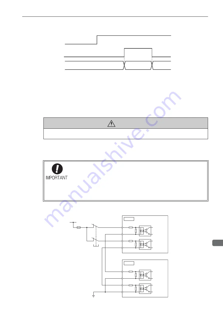
(5) Connection Example and Specifications of Input Signals (HWBB Signals)
The input signals must be redundant. A connection example and specifications of input signals (HWBB sig-
nals) are shown below.
Connection Example
/HWBB1
/HWBB2
/S-ON
SERVOPACK
state
ON ON
HWBB state
BB state
Operating
OFF
OFF
(Motor current
shut-off request)
ON (Normal operation)
CAUTION
• The safety function signal input timing error alarm (A.Eb1) is not a safety-related part of a control system. Keep this
in mind in the system design.
For safety function signal connections, the input signal is the 0 V common and the output
signal is the source output. This is opposite to other signals described in this manual. To
avoid confusion, the ON and OFF status of signals for safety functions are defined as fol-
lows:
ON: The state in which the relay contacts are closed or the transistor is ON and current
flows into the signal line.
OFF: The state in which the relay contacts are open or the transistor is OFF and no cur-
rent flows into the signal line.
CN8
CN8
24-V
power
supply
Fuse
Switch
/HWBB1+
/HWBB1-
/HWBB2+
/HWBB2-
SERVOPACK 1
4
3
6
5
0 V
/HWBB1+
/HWBB1-
/HWBB2+
/HWBB2-
SERVOPACK 2
4
3
6
5
Use a switch that has
micro-current contacts.