YASKAWA MicroTrac Gateway Manual Download Page 23

GENERAL OPERATION

20

PAC Considerations

12/22/94- RD 3196-10

PAC
Considerations

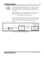
PLC initialization can access both RDCI and GETN blocks.  The only
difference between these blocks is the way each uses the battery backed up
memory (NVRAM – nonvolatile random access memory).  The RDCI block
immediately writes directly to nonprotected NVRAM.  The GETN block does
not automatically write to NVRAM.  Changes made to GETN values will be
lost on drive power down unless a "save to NVRAM" procedure is executed
(function 994).  GETN values are saved to "protected" NVRAM.  A hardware
slide switch on the DSD board must be on to allow this save.  See the DSD
manual for more information.  VCD 703 drives do not have "protected"
NVRAM, so the execution of F994 would save all GETN values to
"nonprotected" NVRAM.

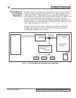
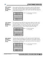
The PAC programmer will need to know how PLC initializations fit into the
overall handling of drive setup parameters in the PAC diagram.  Just as the
PLC initialization table allows the PLC to access drive setup parameters
(function number values), the RDU initialization table allows an RDU access
to these functions.  Figure 11 expands the Figure 9 example to show a remote
display (RDU) initialization table.

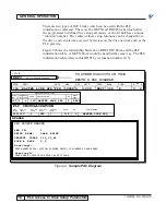
Figure 11.  Sample PAC Diagram

300-E

TO OTHER CIRCUITS IN THIS
DRIVE'S PAC DIAGRAM

F# 115  MASTER LINE SPD

RDCI

FCTN

115

0  0

DESC

UNIT

MAX

MIN

DFLT

TYPE

BLCK

SCAN

DP

P

S

REMOTE DISPLAY LIST

Node  Chan Menu
No.    No. Item

103 5  6  115 MASTER LINE SPD  0  RDCI

FCTN   DESCRIPTION                   DP

Block
Type

PLC INITIALIZATION

PLC    PLC In    PLC In   PLC Out   PLC Out      FCTN      DP           DESCRIPTION
Node   Chan      Item     Chan      Item

200 120   1    020   1      115   0   MASTER LINE SPD

HEADER

PAC SOURCE HEADER

LAN ID:
DRIVE NAME:
PRODUCT CLASS
SCAN A RATE

1
LEAD DRIVE
312_V9 _R1
0.0

Gre eting1:

THIS MAGNETEK DSD (DIGITAL SYSTEMS DRIVE) IS POWERED UP AND READY

Gre eting2:

THERE ARE NO FAULTS TO REPORT AT THIS TIME

MASTER_LINE_SPD FPM

10000 0

1000

RDCI 300

E

Summary of Contents for MicroTrac Gateway

Page 1: ...ior consent Products which the Company consents to have returned shall be shipped prepaid f o b the Company s factory The Company cannot assume responsibility or accept invoices for unauthorized repai...

Page 2: ...Trasfer 17 PAC Considerations 20 TROUBESHOOTING JARC BOARD 22 TROUBLESHOOTING SmartMUX BOARD 23 TROUBLESHOOTING A B PLC 5 or PLC 3 23 PCDU TERMINAL OPERATION 24 Block 0 Gateway Set Up 25 Information...

Page 3: ...0 List of Tables Table Number Title Page 1 JARC Jumper Selection 3 2 JARC Board SW1 DIP Switch Positions 1 8 4 3 JARC Board SW1 DIP Switch Positions 9 11 4 4 JARC Board SW1 DIP Switch Position 12 5 5...

Page 4: ...d and a power supply The NEMA 1 enclosure contains the electronics with internal connections for AC power digital I O points and external connections for the MicroTrac LAN The initial setup is factory...

Page 5: ...switches on the SmartMUX board labeled SW1 and SW2 set the rack address and the baud rate for the communications Refer to Figure 2 Figure 2 SmartMUX Board J1 EPROM I O Rack Connector J2 PWR LED Red fo...

Page 6: ...1 fuse This fuse protects the 5V power to the PCDU Positions 1 through 8 of DIP switch SW1 determine the LAN node address Usually this address is set for 200 when the system has only one PLC gateway T...

Page 7: ...ble 2 JARC Board SW1 DIP Switch Positions 1 8 MICROTRAC SW1 DIP Switch Position LAN LSB MSB ADDRESS 1 2 3 4 5 6 7 8 200 X X X O X X O O 201 O X X O X X O O 202 X O X O X X O O 203 O O X O X X O O 204...

Page 8: ...ard LED Operation LED COLOR DESCRIPTION PWR RED ON when the JARC board has proper 5V power from the power supply The power LED should always be ON RECON YELLOW ON when a LAN reconfiguration occurs Eac...

Page 9: ...SW2 to select the rack address and baud rate The rack address must be consecutive between zero and seven inclusive and must match the rack address set on the JARC board The first DIP switch SW1 contr...

Page 10: ...Switch ON O Open switch Switch OFF Table 9 SmartMUX Board Watchdog Switch DIP Switch SW1 WATCHDOG Position 5 DISABLE WATCHDOG X ENABLE WATCHDOG O DEFAULT X Closed switch Switch ON O Open switch Switc...

Page 11: ...ddresses of the 8 I O points range from I XX0 10 to I XX0 17 for inputs and O XX0 10 to O XX0 17 for outputs where XX is the Gateway rack number octal These I O must be all inputs or all outputs Table...

Page 12: ...rt of the specification the SmartMUX board must meet A user must place a terminating resistor on both physical ends of a remote I O link to ensure proper operation NOTE Refer to Allen Bradley s 1785 P...

Page 13: ...ted as a remote I O rack by the PLC From a PLC 5 the selected rack number can be between 1 and 7 inclusive From a PLC 3 the rack number can be between 0 and 7 Note that the PLC gateway is configured a...

Page 14: ...I notation Thus LAN CHANNEL 124 INPUT RACK 2 GROUP 4 or I 24 LAN CHANNEL 127 INPUT RACK 2 GROUP 7 or I 27 The sub channel number will also be in octal and will directly correspond to the bit number of...

Page 15: ...number Thus LAN CHANNEL 015 OUTPUT RACK 1 GROUP 5 or O 15 The sub channel number will also be in octal and will directly correspond to the bit number of the simulated input Thus the 16 possible bits a...

Page 16: ...eading digit must be a 1 The SmartMUX board only supports Numeric block transfers to slot 0 and group 0 Thus LAN CHANNEL 130 RACK 3 GROUP 0 The PAC block s sub channel number will be in decimal and wi...

Page 17: ...umeric outputs except that the leading digit is always 0 The SmartMUX board only supports Numeric block transfers to slot 0 and group 0 Thus LAN CHANNEL 030 RACK 3 GROUP 0 The PAC block s sub channel...

Page 18: ...nit RDU or a personal computer TracView display The subsequent programming techniques make sure that a change from one device is reflected at the other device and establish when one device takes prece...

Page 19: ...d the same way The PLC initialization table refers to this RDCI by its function number 115 Figure 9 Sample PAC Diagram 300 E TO OTHER CIRCUITS IN THIS DRIVE S PAC DIAGRAM F 115 MASTER LINE SPD RDCI FC...

Page 20: ...e PLC gateway detects a change in data from the PLC the appropriate drive is updated with the new data The data transition initiates this exchange This new value is returned to the PLC as confirmation...

Page 21: ...locks with the decimal point DP parameter As shown in Figure 10 the DP for the pertinent NUMI block must be specified as 2 In some cases a 16 bit signed integer 32 768 may not be sufficient for the re...

Page 22: ...ue PLCTODSD Data transferred from the PLC to the Drive LOAD_PLC MOV 0 Move Source PLC_DATA 0 Dest PLCTODSD 0 NEQ MOV 1 Not Equal A B Move A DSDTOPLC Source DSDTOPLC 0 0 B DSDTOPLC_OLD Dest PLCTODSD 0...

Page 23: ...ions fit into the overall handling of drive setup parameters in the PAC diagram Just as the PLC initialization table allows the PLC to access drive setup parameters function number values the RDU init...

Page 24: ...e number which is usually 200 but could be 200 210 2 A decimal location is independently assigned in each row The SCDU PCDU RDU and PLC can each have different decimal locations 3 The PAC channel in t...

Page 25: ...reconfiguration A reconfiguration occurs when ever a new node enters the network During power up start up or initialization of any node on the network this LED will turn ON for approximately 1 second...

Page 26: ...odd rack address or twice if the node is an even rack address COMM GREEN When the Allen Bradley PLC establishes communication with LED1 the SmartMUX board this LED will flash or be ON A flashing COMM...

Page 27: ...row and ENT enter The diagnostic information is a circular list This display can be changed by pressing the INC or DEC keys Pressing the INC key displays the next line of information and pressing the...

Page 28: ...l This block displays the digital logic data read by the PLC from the remote I O rack simulated by this gateway This is shown by the abbreviation Dig Rd followed by the rack and group number a dash an...

Page 29: ...viation Dig Wr followed by the rack and group number a dash and the sixteen bit digital value displayed in hexadecimal representation Dig Wr Y0 Where Y is the unused rack number Dig Wr Y1 is the data...

Page 30: ...is shown by the abbreviation Blk Wr followed by the rack number a dash the element number within the block a dash and the sixteen bit value displayed in hexadecimal representation A block transfer co...

Page 31: ...his gateway This is logic data to be written to the gateway from the drive indicated by the node number The channel number agrees with the channel specified by the LOGO element LOGO NN CCC Where NN is...

Page 32: ...e diagnostic displays shows the NUMO memory allocations in this gateway This is numeric data to be written to the gateway from the drive indicated by the node number The channel number agrees with the...

Page 33: ...istered trademarks of the Allen Bradley Company Inc SmartMUX is a trademark of Western Reserve Controls Inc Yaskawa Electric 16555 W Ryerson Road New Berlin Wisconsin 53151 800 541 0939 262 782 0200 F...

Reviews: