


8
HARDWARE
SmartMUX Board LED Operation
12/22/94- RD 3196-10
SmartMUX
Board LED
Operation
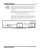
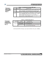
There are two LEDs on the SmartMUX board; one status LED and one
communications LED. The function of these LEDs is listed in Table 11.
The placement of the LEDs is shown in Figure 2.
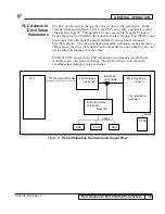
The PLC gateway has local I/O connection points. The SmartMUX board connects
to a local I/O interface board which has 8 logic inputs or logic outputs that can be
either AC or DC. The local interface I/O are always assigned to module group 0,
slot 1 of the rack being simulated by the SmartMUX board. These I/O can be
accessed by the PLC directly, but not by devices on the drive network.
The addresses of the 8 I/O points range from: I:XX0/10 to I:XX0/17 for inputs,
and O:XX0/10 to O:XX0/17 for outputs, where XX is the Gateway rack number
(octal). These I/O must be all inputs or all outputs.
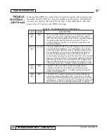
Table 11. SmartMUX Board LED Operation
LED
COLOR
DESCRIPTION
STATUS
RED
When the SmartMUX board has 5V power from the
(PWR)
power supply, this LED will flash once or twice and then turn
OFF. If the LED flashes once, then this node is an odd rack
address. If the LED flashes twice, then this node is an even
rack address.
COMM
GREEN
When the Allen-Bradley PLC establishes communications with
(LED1)
the SmartMUX board, this LED will flash or be ON. A flashing
LED means the PLC is in program mode. A solid or ON LED
means the PLC is in run mode and information is being
transferred. Proper operation with the PLC in run mode
results in this LED being ON.
Local I/O Racks


