background image

Maintenance and inspection

9

 - 

71

9.6

Setting the second home position (check point)

9.6.1

Purpose of position check operation

If the absolute number of rotations detected when the power is switched on does not match
the data stored by the absolute encoder the last time the power was switched off, an error
message is output.
There are two possible causes of this error message:

Error in the pulse generating system

The robot was moved after the power supply was turned OFF

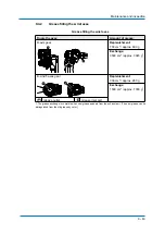
If the alarm "OUTSIDE THE RANGE (ABSOLUTE DATA)" appears, automatic mode is not
possible. The home position must be checked.

If the "OUT OF RANGE (ABSO DA-
TA)" alarm occurs:

Compare second home position 
(check point)* with current position 
pulses.

Alarm reset

The alarm occurs again

Switch the servo power on

Correct the faulty axis, replace the 
pulse generating system, set the 
home position

Procedure after an alarm

* Position checking point

Position confirmation

Automatic mode possible

OK

NOK

1

6

2

7

3

8

4

9

5

10

Summary of Contents for MH50II

Page 1: ...ROBOTICS MH50II YR MH00050 J00 Operating and Maintenance Manual ...

Page 2: ...mber E1101000183GB08 Author WOE Changes made in revision Rev 01 Revised version of the original HW1482719 0 in YEU style 2014 05 Rev 02 Revised version of the original HW1482719 1 2014 08 Rev 03 Revision of table Inspection intervals and review of chapter Grease replenish ment exchange 2015 03 Rev 04 Revised version of the original HW1482719 2 2015 04 Rev 05 Review of chapter Grease replenishment ...

Page 3: ...installation location 19 4 3 Installation example 20 5 Wiring 25 5 1 Grounding 25 5 2 Cable connections 26 5 2 1 Connecting the robot 27 5 2 2 Connection of the robot controller 28 5 2 3 Connecting the programming pendant 29 6 Technical data 30 6 1 Parts and work axis label 31 6 2 Robot base dimension 31 6 3 Dimensions and defined working area 32 6 4 Adjustable working area 33 6 4 1 Instructions f...

Page 4: ...4 1 Grease filling the main axes 62 9 4 2 Grease filling the wrist axes 63 9 5 Home position calibration 64 9 5 1 Register all axes 65 9 5 2 Register individual axes 68 9 5 3 Changing absolute data 69 9 5 4 Clearing absolute data 70 9 6 Setting the second home position check point 71 9 6 1 Purpose of position check operation 71 9 6 2 Procedure for the second home position setting 73 9 6 3 Procedur...

Page 5: ...s NOTICE Indicates important background information and application advice 1 2 Frequently used terms The YASKAWA robot is a product of YASKAWA Electric Corporation and is provided by default with the robot control the programming pendant and robot cable The terms are designated as follows in this manual Term Description Control Robot control Industrial robot Robot Programming pendant teach box Pro...

Page 6: ...t system must receive training before they operate the robot For optimal use of our products we recommend our customers to take part in a training session at the YASKAWA Academy For more detailed information on the training programme please visit www yaskawa eu com or directly get in touch with your YASKAWA branch office 1 4 Intended use Typical applications Flange mounting tools Installation of s...

Page 7: ...g holes or similar modifications can damage parts This will be regarded as improper use i e use that deviates from the intended use and will lead to loss of warranty and liability claims as well as loss of the declaration of incorporation CAUTION The robot system is an incomplete machine The robot system may be put into operation only after it has been determined that the incomplete or complete ma...

Page 8: ... shields removed All protective covers and shields must be mounted before the robot is operated The drawings and figures in this manual are representative illustrations They may differ from the product delivered YEU R reserves the right to make technical changes These changes may include product improvements modifications or changes in specifications If your copy of the operating and maintenance i...

Page 9: ...Stop button 1 Short Cut Main Menu JOB CONTENT 0000 0001 0002 0003 0004 0005 0006 0007 0008 0009 0010 0011 TEST01 TOOL CONTROL GROUP R1 S 0000 NOP SET B000 1 SET B001 0 MOVJ VJ 80 00 MOVJ VJ 80 00 DOUT OT 10 ON TIMER T 3 00 MOVJ VJ 80 00 MOVJ VJ 100 00 MOVJ VJ 100 00 MOVJ VJ 100 00 MOVJ VJ 100 00 Turn on servo power JOB EDIT DISPLAY UTILITY MOVJ VJ 0 78 S SELECT X S X L Y L Y U Z U Z R X R X B Y B ...

Page 10: ...operations within the robot s working range View the Robot from the front whenever possible Always follow the prescribed operating procedure see the instructions on robot control as well as the operating instructions on Handling or Universal Application An area must be left clear so that the operator can retreat to it in case of emergency The following inspection procedures must be performed prior...

Page 11: ...Manufacturer Address YASKAWA ELECTRIC CORPORATION 2 1 KUROSAKISHIROISHI YAHATANISHI KU KITAKYUSHU JAPAN 1 9 Authorized representative Address YASKAWA Europe GmbH Robotics Division Yaskawastr 1 85391 Allershausen Germany ...

Page 12: ...2 1 Checking the scope of delivery The standard delivery includes the following items Fig 2 1 Scope of delivery Programming pendant Assembly instruction Robot controller Cable Robot MOTOMAN MANUAL 1 2 3 5 4 DX200 1 4 2 5 3 ...

Page 13: ...ate NOTICE Please contact the local YASKAWA branch office if the serial numbers do not match the information on the delivery note S N DX200 YASAKAW XXXXX Part No Power Supply Peak kVA AC XXXXXXXX Average kVA Serial No Date Signature Type ERDR Robot Type Robot Order No Robot Serial No YASKAWA ELECTRIC CORPORATION 2 1 SHIROISHI KUROSAKI YAHATANISHILU KITAKYUSYU JAPAN YASKAWA Europe Robotics Division...

Page 14: ... exerted on the robot controller on the robot or on other components 3 1 Transporting method CAUTION Damage to persons and damage to property due to external force influences External forces must not be exerted on the robot or the motors Check that the eyebolts are securely fastened The robot weights approximately 550 kg Use load carrying devices strong enough to withstand the weight The transport...

Page 15: ... Using a crane Adequate load handling devices must be used to transport the robot Make sure that the robot is lifted as shown in the diagram Transport by crane Fig 3 1 Transport with crane 8 screws M12 Shipping bracket 2 1 1 2 ...

Page 16: ...transport securing devices and shipping bolts as shown in the figure below Transport using a forklift Make sure that the forklift and the transportation route have sufficient bearing capacity Always take due care when transporting the robot Fig 3 2 Using a forklift 8 M20 screws Openings for the fork prongs Pallet 1 2 3 1 3 2 ...

Page 17: ...are removed After removing the transport securing devices and the shipping bolts keep them at a safe place The transport securing devices and shipping bolts will be required again if the system is transported again The robot is equipped with transport securing devices and shipping bolts to reduce external forces to a minimum during transport ...

Page 18: ...e protective measures can lead to death of people serious bodily harm or material damage Implement the following protection measures Separating protection devices Non contact protection devices Enclosures Marked areas Signs Emergency Stop button Display elements NOTICE Operator s responsibility The operator of a robot or a robot system must ensure that all specifications and requirements of the st...

Page 19: ...undermentioned environmental conditions Ambient temperature from 0 C to 45 C Air humidity 20 to 80 relative humidity non condensing Free of corrosive gases liquids or explosive gases Free from excessive vibration Vibration acceleration 4 9 m s 0 5 G or less Maximum unevenness of the support surface of the robot base 0 5 mm ...

Page 20: ...e base plate Tighten the hexagon head bolts and anchor bolts securely so that they will not work loose during operation see figure Mounting of the robot on the base plate Fig 4 1 Mounting the robot on the base plate Screws at least 30 mm Sprirng washer Anchor bolt M2 or greater Washer 2 holes Ø 12 H7 Robot base 8 Holes Ø 22 Base plate adhesive 8 10 1 2 3 4 5 7 5 6 9 230 400 195 0 1 230 0 1 195 0 1...

Page 21: ...e NOTICE YASKAWA Europe recommends to use the robot only with a base plate Please contact the manufacturer of the mounting material you use 1000 1000 900 710 500 500 710 900 180x45 320 385 230 400 26 12x M20 8x 360 360 M 1 6 8 x 0 2 30 5 ...

Page 22: ...grease inlet opening see the figures below This is to prevent grease from emerging from the grease discharge aperture In a wall mounting you must assemble the robot with the plug plate facing up see the picture for wall mounting Direction of move ment Horizontal Vertical Force FH Moment MH Force FV Torque MV Emergency stop Stop category 0 23544 N 24525 Nm 27468 N 45126 Nm Acceleration Decelera tio...

Page 23: ...he ceiling Grease outlet opening View Grease inlet opening Before the mounting to the ceiling Motor base plate View A Grease outlet opening Before the mounting to the wall Grease inlet opening Power input module After the mounting to the wall A 1 2 3 3 2 4 6 5 1 4 2 5 3 6 1 2 3 4 5 6 3 2 7 A 1 5 2 6 3 7 4 ...

Page 24: ...range For the wall mounted type the S axis movable range is 30 the range is adjusted prior to the shipment Fastening the robot base With suspended mounting the robot must be fastened with 4 screws M20 Strength category 12 9 Use a torque of 700 Nm in tightening the screws Precaution against falling In case of suspended mounting take measures to prevent the robot from falling down NOTICE If the setu...

Page 25: ...rds and wiring regulations for earthing The cable cross section must be 6 mm or more For information on connecting the earthing cable directly see Fig 5 1 Earthing connection NOTICE Note on the earthing connection Never use the earthing cable together with an earthing cable of for example A different electrical consumer A different motor driven consumer Welding devices etc If the earthing cable is...

Page 26: ...the robot base and on the robot controller see the following chapter on robot connection and robot controller connection Fig 5 3 Robot cable Robot control side Encoder cable 1BC Robot side Power cable 2BC DX200 YASAKAW DX200 Part No Power Supply Peak kVA AC 400 415 440 Average kVA Serial No Date Signature Type ERDR Robot Type Robot Order No Robot Serial No YASKAWA ELECTRIC CORPORATION 2 1 SHIROISH...

Page 27: ...er cable 2BC 2 Connect the encoder cable 1BC to the connector plate of the robot 3 Connect the power cable 2BC to the connector plate of the robot Make sure that you hear each locking clip snap into place clicking sound Fig 5 4 Connector plate of the robot 5 AIR 1BC 2BC 2BC 1BC AIR ...

Page 28: ... order 1 Connect the encoder cable 1BC X11 at connection X11 to the robot controller 2 Connect the power cable 2BC X21 at connection X21 to the robot controller Make sure that you hear the locking clips snap into place clicking sound Fig 5 5 Connection of the robot controller X 11 X 21 X 1 X 2 ...

Page 29: ...1 PROGRAMMING PENDANT PROPERLY CHECK ALL THE DOOR LOCKS NJ3005 1 kVA kVA ERDR Average Peak NJ3053 1 Kammerfeldstr 1 D 85391 Allershausen 2 1 Kurosaki Shiroishi Yahatanishi Ku Kitakyushu City Fukuoka 806 0004 Japan YASKAWA Electric corporation Robot Serial No Robot Order No Robot Type Type Date Signature Serial No AC 400 415 440 V Power Supply Part No Motoman DX100 with power ON WARNING Do not open...

Page 30: ...s wrist twist 360 360 Protection class IP Main axes 54 Wrist axis 67 Maximum speed S axis 3 14 rad s 180 s L axis 3 11 rad s 178 s U axis 3 11 rad s 178 s R axis 4 36 rad s 250 s B axis 4 36 rad s 250 s T axis 6 28 rad s 360 s Admissible moment Nm 3 3 See the following diagram Moment of arm rating in section 7 for further information on the permissible moment of inertia R axis 216 Nm B axis 216 Nm...

Page 31: ...ion Fig 6 2 Robot base dimensions Upper arm U arm Rotating head of S axis Wrist flange Robot base Lower arm L arm 2 holes Ø 12 H7 8 mounting holes Ø 22 All dimensions in mm 1 2 3 5 4 T T B B R R U U L L S S 1 4 2 5 3 230 400 195 0 1 230 0 1 195 0 1 195 0 1 320 385 230 0 1 195 0 1 455 608 455 153 280 1 2 1 2 ...

Page 32: ...t Working area defined with point P All dimensions in mm 210 870 540 187 1807 120 87 213 605 1056 1771 248 530 543 2061 3832 0 145 1025 175 437 925 2456 460 1121 3578 0 1 3 5 90 5 5 170 118 1369 453 0 105 105 57 223 5 40 3 4 3 3 5 2 234 234 T R U S L B R543 R2061 50 50 200 611 5 100 98 5 50 50 R377 2 2 1 1 2 ...

Page 33: ...he work area of the s axis may be changed depending on the type of application If any modification is necessary please contact the local YASKAWA branch office Item Specifications S axis working range 180 standard 165 150 135 120 105 90 75 60 45 30 15 ...

Page 34: ...crews with a tightening torque of 700 Nm With a working area of 180 the stop must be mounted as shown in the figure Components of the S axis limit The stop can be mounted at 15 degree intervals To avoid a mechanical interference from stop duplication eg 15 165 install the mechanical stop as shown in the following table 6 4 3 Adjusting the S Axis Pulse Limit NOTICE Always use the specified componen...

Page 35: ...ing the Working Area To change the working area of S axis the following components are required see the following figure Fig 6 4 Components of the S axis limit Sleeve HW9405875 2 Washer M6 x3 Screw M20 x 40 Pin HW9405032 2 1 2 3 4 standard 1 3 2 4 ...

Page 36: ...Pulse limit positive direction of S axis SICxG400 Pulse limit negative direction of S axis SICxG408 NOTICE To change the movement range of the machine set both the pulse limit and the angle of the mechanical S axis limit Degress 15 30 45 60 75 90 Number of pulses 0 21203 42406 63609 84812 106015 127217 Degress 120 135 150 165 180 standard Number of pulses 14842 0 16962 3 190826 212029 233232 25443...

Page 37: ...n times may differ due to internal and external influence on the braking torque According to the mode robot application and number of triggered safety stops with stop category 0 a different brake wear may occur We recommend that the coastdown path be checked once a year Fig 6 5 Main axes at 100 66 and 33 deflection In Fig 6 5 Main axes at 100 66 and 33 deflection the S L and U axes are shown at 33...

Page 38: ...Technical data 6 38 6 5 1 Stop category 0 6 5 1 1 Stop position S axis 100 deflection 66 deflection 33 deflection deg deg s deg s sec deg deg s deg s sec deg deg s deg s sec ...

Page 39: ...Technical data 6 39 6 5 1 2 Stop position L axis 100 deflection 66 deflection 33 deflection deg deg s deg s sec deg deg s deg s sec deg deg s deg s sec ...

Page 40: ...Technical data 6 40 6 5 1 3 Stop position U axis 100 deflection 66 deflection 33 deflection deg deg s deg s sec deg deg s deg s sec deg deg s deg s sec ...

Page 41: ...e not subjected to the robot position and the load Stop of category1 doesn t depend on the robot position and the load 6 5 2 1 Stop position S axis 100 deflection 6 5 2 2 Stop position L axis 100 deflection 6 5 2 3 Stop position U axis 100 deflection deg deg s deg s sec deg deg s deg s sec deg deg s deg s sec ...

Page 42: ...NOTICE Before mounting a tool remove anticorrosive coating on the flange Thinner or light fuel oil are the most suitable for this purpose 7 2 Maximum load of the S axis For peripheral devices of specific applications additional mounting options are provided on the robot 7 3 Optimal robot performance To achieve optimal robot performance the maximum load of the S axis must never exceed the permissib...

Page 43: ...to the following figure Hand loads Fig 7 1 Moment of arm rating The peripheral devices are mounted on the upper arm of the U axis and the rotating head of the S axis see the following figure to facilitate the installation of the system applications of the user The following conditions should be observed to attach or install peripheral equipment Axis Permissible torque Nm Permissible moment of iner...

Page 44: ... 4 threaded holes M8 x 16 4 threaded holes M12 x 18 All dimensions in mm Section Notice A Up to 50 kg for attaching load mass including wrist load B maximum 10 kg 49 N m 5 kgf m max for increased moment amount of upper arm C Up to 30 kg only for floor and ceiling mounted types 180 60 100 98 5 50 50 60 60 10 B 2 3 200 513 100 50 100 40 223 5 187 57 105 105 A A C 1 4 1 3 2 4 ...

Page 45: ...axis varies and depends on the permissible torque Contact your YASKAWA branch office in a timely manner if you have questions regarding the calculation of the load or centroidal distance Example In the case of the YASKAWA HP20D robot for example the permissible moment of inertial for the T axis amounts to 0 25 kgm at a permissible torque of 19 6 Nm and to 0 75 kgm at a permissible torque of 0 1 Nm...

Page 46: ...ing requirements must be met The total current value for the internal wiring harness must be 34 5 A The current carrying capacity per single conductor cross section 0 50 mm must not exceed 5 1 A or less The air pressure for the air hose must not exceed 600 kPA the inner diameter of the air hose is Ø 8 mm Fig 8 1 Connectors for internal user I O wiring harness and air line Connector plug for the in...

Page 47: ...ans of single wires The internal connections of the robot are shown in the following diagrams Connection diagram A and Connection diagram B assigned unassigned Pins used Internal user I O wiring harness 23 wires 0 5 mm 2 8 4 9 6 5 1 7 2 3 14 19 20 15 17 11 12 18 13 21 22 23 10 16 P P P P P P P P P P P 1 6 5 3 4 2 7 8 9 10 15 14 13 12 11 20 19 17 18 16 22 23 21 1 1 2 ...

Page 48: ...1 P BAT 6 X 3 1 3 No 24CN 1 24V 0V 4 2 2 4 24V 0V 1BC 10 4 0V 24V CN1 5 CN1 4 P SPG 1 SPG 1 0V 24V CN1 2 CN1 1 CN1 9 CN1 10 P P FG1 CN1 3 SPG 2 SPG 2 CN1 7 CN1 6 P CN1 5 0V 24V CN1 10 CN1 1 CN1 9 0V SPG 1 SPG 1 24V CN1 4 DX100 CN1 3 FG1 CN1 6 CN1 7 SPG 2 SPG 2 CN1 2 8 10 4 9 0V BAT OBT FG2 5V 2 5 6 3CN 1 No 3CN DATA 3 DATA 3 OBT BAT P U P P 9 10 0V OBT BAT FG3 P R P P 4 5V 4 3 No 20CN 2 1 4 No 21C...

Page 49: ...1 1 1 1 1 1 1 1 1 1 1 1 1 0 09 08 08 09 0 0 09 1 1 1 1 1 1 1 1 1 1 1 1 1 1 1 1 1 1 1 09 09 0 08 09 0 1 1 1 1 1 1 1 1 1 1 1 1 1 1 1 1 1 1 1 1 1 1 1 1 60 60 60 1R 1 1 0 08 09 0 1 08 09 09 0 08 08 08 0 1 1 1 1 1 1R 1 08 0 0 09 1R 1 1 0 09 08 0 0 08 1 1 1 1 1 1 1 1 1 1 1 1 1 1 1 1 1 1 1 1 1 1 1 1 1 1 1 1 60 60 60 1R 1 3 09 0 0 1 1R 1 08 08 1 3 09 0 0 1 1R 1 08 09 3 0 0 3 S AXIS L AXIS U AXIS B AXIS R ...

Page 50: ...king maintenance and inspection measures Turn OFF the main power supply Put up the required warning sign e g Do not turn the power on Install a switch on guard as prescribed If you have any questions regarding disassembly or repair please contact the local YASKAWA branch office NOTICE Home position data is lost Before removing the connector of the encoder cable to perform maintenance or inspection...

Page 51: ... intervals SYS MONITORING TIME DATA EDIT DISPLAY UTILITY Main Menu ShortCut CONTROL POWER TIME 1998 07 06 10 00 2385 42 02 SERVO POWER TIME 1998 07 06 10 30 36000 00 00 PLAYBACK TIME 1998 10 22 11 12 2210 00 20 MOVING TIME 1998 10 22 15 30 1875 15 30 OPERATING TIME 1998 10 22 16 12 0 0 0 1 Short Cut Main Menu JOB CONTENT 0000 0001 0002 0003 0004 0005 0006 0007 0008 0009 0010 0011 TEST01 TOOL CONTR...

Page 52: ...orking area and robot Visual inspection If the working area is dirty it must be cleaned Check the robot for damage and external cracks 4 Motors for S L U R B and T axis Visual inspection Check for grease discharge 2 5 Fastening bolts of the base plate Using a correspond ing tool tighten loose screws replace if necessary 6 Fixing screws of the cover Using a correspond ing tool tighten loose screws ...

Page 53: ...ews replace if necessary 11 Battery unit in robot If a battery alarm appears or after the robot has been operated for 36000 hours the battery must be exchanged 12 S L U R B and T axes gear Grease gun Check for malfunctions replace if necessary The grease4 must be refilled every 6000 hours and exchanged every 12000 hours see Chapter 9 4 1 Grease filling the main axes and 9 4 2 Grease filling the wr...

Page 54: ...ranch office 3 When checking for conduction with multimeter connect the battery to BAT and OBT of the plug connections of the respective motor Now remove the connectors of the encoders of the respective motor Failure to observe this sequence can lead to loss of home positions see section 9 3 1 Wrist unit on page 59 4 The grease or lubricants used can be found in the following table Inspection poin...

Page 55: ...Maintenance and inspection 9 55 Fig 9 2 Inspection intervals AIR 1BC 2BC ...

Page 56: ...ry pack has to be changed in the following form 1 Turn the robot controller to the main power supply see Fig 9 4 Main power switch in switch off position Fig 9 4 Main power switch in switch off position 2 Remove the fixing screws from the cover plate Battery holder Battery pack Mounting screws of cover plate Power input module Main power switch in switch off position AIR 1BC 2BC 1 2 3 4 1 3 2 4 wi...

Page 57: ...attery holder NOTICE The absolute encoder data will be lost Never remove old battery pack before having installed new battery pack 7 Please remove old battery pack plug from circuit board NOTICE Make sure that no wires are pinched when you install the battery pack and the cover plate again 8 Please apply Teroson Plast sealing compound material no 143813 to thread part of screws Exchanging the batt...

Page 58: ...Battery unit connector diagram for R B and T axes Motor Battery unit Motor power connector Plug for backup Encoder connector Encoder Warning label Motor cable Power connector Battery unit Wiring harness of the robot a Plug socket b Plug pin Motor Encoder connector b a a b OBT BAT BAT OBT 4 1 2 3 5 1 4 2 5 3 Connect battery to encoder to save the data before removing connector CAUTION OBT BAT OBT4 ...

Page 59: ...nnect the battery pack to the battery backup connector before removing the encoder connector The battery connectors are dealt with in the chapter 9 2 1 Changing battery unit on page 56 9 3 1 Wrist unit The motor and encoder units are provided with the wrist unit To prevent fumes penetrating into wrist unit matched parts are sealed If you have removed the wrist cover the seal must be replaced with ...

Page 60: ... Do not install a joint hose etc to the grease outlet If this instruction is not followed the motor will be damaged Avoid air getting into the gear Insert grease with a grease gun If an automatic lubricating pump is used the grease supply pressure must be 0 3 kPa Set the grease injection rate to a value not higher than 7 g s The limit values may not be exceeded also if a conventional grease gun is...

Page 61: ...queeze out the excess fat all taxes must be brought to operating temperature In a operating JOB or a special moving JOBs about 20 minutes at 100 speed 5 Wipe away excess grease with a cloth 6 Remove the lubricating nipple from the grease inlet opening and mount the plug again Before mounting the plug apply to thread part Tightening torque the set screw Designation Tightening torque Nm PT 3 8 23 PT...

Page 62: ...0 g1 1 The grease exchange is complete when new grease appears from the exhaust port The new grease can be distinguished from the old grease by color L axis gear Replenishment 250 cm approx 217 g Exchange 1650 cm approx 1435 g1 U axis gear Replenishment 140 cm approx 120 g Exchange 700 cm approx 609 g1 Grease outlet Grease inlet port PT3 8 PT1 4 AIR 1BC 2BC PT3 8 PT3 8 1 2 ...

Page 63: ...s gear Replenishment 700 cm approx 609 g Exchange 3500 cm approx 3045 g1 1 The grease exchange is complete when new grease appears from the exhaust port The new grease can be distinguished from the old grease by color B and T axes gear Replenishment 300 cm approx 260 g Exchange 1500 cm approx 1300 g1 Grease outlet Grease inlet port 1 2 ...

Page 64: ... setting the home position the position of the absolute encoder must match it Although this operation is performed prior to shipment at the factory the following cases require this operation to be performed again Change in the combination of the robot and robot controller Replacement of the motor or absolute encoder Clearing stored memory by replacement of the main CPU board weak battery pack etc ...

Page 65: ...Maintenance and inspection 9 65 9 5 1 Register all axes 1 Select ROBOT from the main menu The sub menu choices appear 2 Select HOME POSITION The HOME POSITIONING window appears ...

Page 66: ... 3 can also be performed by selecting the PAGE button In this case a selection box appears 4 Select the sub assembly to calibrate e g R1 ROBOT Select the control group for HOME POSITIONING The control group can also be selected by pressing page key 5 Select EDIT in the main menu The pull down menu appears ...

Page 67: ...d inspection 9 67 6 Select SELECT ALL AXES A confirmation dialog box is displayed 7 Select YES Displayed position data of all axes are registered as home position When NO is selected the registration will be canceled ...

Page 68: ... be calibrated e g R1 ROBOT Perform steps 3 and 4 as described in section 9 5 1 Register all axes to select the desired control group 4 Move the cursor to the axis you want to register and select it A confirmation dialog box appears 5 Select YES The displayed position data of the selected axis is registered as the zero position If you select NO registration is aborted ...

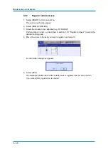
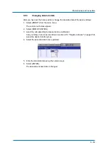
Page 69: ...n menu The sub menu choices appear 2 Select HOME POSITION 3 select the sub assembly components to be calibrated Carry out steps 3 and 4 as described in section 9 5 1 Register all axes on page 65 to select the desired control group 4 Select the absolute data to be registered 5 Enter the absolute data using the numeric keys 6 Select ENTER The absolute encoder data is changed ...

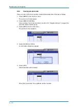
Page 70: ...sub menu choices appear 2 Select HOME POSITION Carry out steps 3 and 4 as described in section 9 5 1 Register all axes on page 65 to select the desired control group 3 Select DATA from the main menu The pull down menu appears 4 Select CLEAR ALL DATA A confirmation dialog box appears 5 Select YES All absolute data will be deleted When NO is selected the registration will be canceled ...

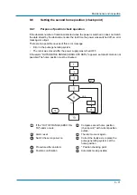
Page 71: ...the pulse generating system The robot was moved after the power supply was turned OFF If the alarm OUTSIDE THE RANGE ABSOLUTE DATA appears automatic mode is not possible The home position must be checked If the OUT OF RANGE ABSO DA TA alarm occurs Compare second home position check point with current position pulses Alarm reset The alarm occurs again Switch the servo power on Correct the faulty ax...

Page 72: ...n 9 6 2 Procedure for the second home position setting on page 73 Alarm message If the alarm occurs again the error may be in the PG system Check the pulse generating system Once you have set the faulty axis set the zero position of the axis and then check the position again NOTICE If you set the zero position simultaneously for all axes automatic mode is possible without a position check However ...

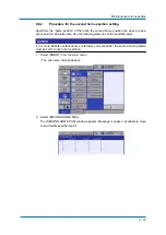
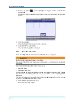
Page 73: ... absolute data Use the following steps to set the specified point NOTICE If 2 or more Robots or stations are controlled by one controller the second home position must be set for each robot or station 1 Select ROBOT from the main menu The sub menu choices appear 2 Select SECOND HOME POS The SECOND HOME POS window appears Message is spoken Available to move to and modify specified point ...

Page 74: ...ction 1 7 Safety on page 9 WARNING Death or injury because of danger of crushing Irregularities in the PG system may lead to an alarm and the robot may perform unexpected movements If the OUT OF RANGE ABSO DATA alarm occurs Reset the alarm the SERVO power ON Then confirm the second home position After the confirmation if the PG system is found to be the cause of the alarm perform the necessary ope...

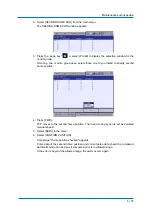
Page 75: ...to you intend to specify second home position 4 Press FWD TCP moves to the second home position The robot moving speed is set as selected manual speed 5 Select DATA in the menu 6 Select CONFIRM POSITION A message Home position checked appears Pulse data of the second home position and current pulse data should be compared Automatic mode can be done if compared error is in allowed range If the erro...

Page 76: ...Sealing compound Teroson Plast 143813 Battery unit Robot 128708 Battery unit Control 155543 Wire harness HW1171766 A 173391 Power input module HW0374034 C 173393 S axis Gear unit HW1382898 A 173386 Input Gear HW0313741 1 146392 Motor SGMRV 30ANA YR1 144108 L axis Gear unit HW9381465 B 112513 Input Gear HW9482771 A 112595 Motor SGMRV 37ANA YR1 144071 U axis Gear unit HW0387753 A 144090 Input Gear H...

Page 77: ...SF22 E 169501 General I O board PNP Type JANCD YIO22 E 164762 Power ON unit Cat 4 JZRCR YPU52 1 164764 Axis board SRDA EAXA21A 170650 Converter module SRDA COA30A21B E 164767 Capacitor module 12A Type SRDA CUA662AA 164781 SERVO Amplifier S SRDA SDA71A01A E 144169 SERVO Amplifier L SRDA SDA71A01A E 144169 SERVO Amplifier U SRDA SDA35A01A E 155478 SERVO Amplifier R SRDA SDA14A01A E 144168 SERVO Ampl...

Page 78: ...1 78 11 Parts lists 11 1 S axis drive Fig 11 1 S axis drive 1019 1001 1002 1003 1004 1005 1007 1009 1008 1010 1011 1013 1014 1016 1018 1020 1017 1021 1022 1025 1026 1028 1023 1024 1012 1030 1033 1029 1032 1031 1035 ...

Page 79: ...012 C 30 SG 22A Grommet 1 1013 M12 x 55 Screw 3 1014 2H 4 Washer 3 1016 STW 50 Retaining ring C type 1 1017 M8 x 100 Screw 1 1018 2H 4 Washer 1 1019 PT3 8 Set screw 1 1020 MSTH10 25 Pin 1 1021 M12 x 55 Screw 12 1022 2H 4 Washer 12 1023 HW9405875 1 Washer 1 1024 M20 x 40 Screw 1 1025 HW0102236 1 Housing 1 1026 KQ2L10 01S Elbow 1 1028 NB 1075 0 43 Hose 1 1029 HW0314010 1 Housing 1 1030 Y507212 5 Oil...

Page 80: ... lists 11 80 11 2 L axis unit Fig 11 2 L axis drive 2002 2005 2016 2004 2003 2026 2009 2008 2006 2007 2026 2027 2027 2027 2017 2011 2013 2014 2015 2010 2019 2020 1009 2001 2021 2022 2024 2023 2018 2025 2025 ...

Page 81: ...008 M16 x 45 Screw 6 2009 2H 16 Washer 6 2010 HW9481343 A Shaft 1 2011 HW9482771 A Gear box 1 2012 HW9405902 1 Pipe 1 2013 M8 x 130 Screw 1 2014 2H 8 Washer 1 2015 M8 Washer 1 2016 G270 O ring 1 2018 HW0314011 1 Housing 1 2019 HW0312815 2 Gear box 1 2020 HW9482447 A Oil seal 1 2021 M12 x 65 Screw 4 2022 2H 12 Washer 4 2023 M6 x 30 Screw 2 2024 2H 6 Washer 2 2025 EZ5002A0 Plug 3 2026 PT3 8 Set scre...

Page 82: ...Parts lists 11 82 11 3 U axis drive Fig 11 3 U axis drive 2002 3014 3015 3028 3023 3024 3007 3027 3017 3022 3001 3016 3021 3026 3025 3018 3008 3009 3011 3010 3005 3006 3020 3019 3002 3004 3003 3012 3015 ...

Page 83: ...W8411125 3 Washer 1 3010 M6 x 115 Screw 1 3011 2H 6 Washer 1 3012 M12 x 30 Screw 12 3013 2H 12 Washer 12 3014 M10 x 30 Screw 6 3015 2H 10 Washer 6 3016 HW9405257 1 Sleeve 1 3017 HW0102239 2 Housing 1 3018 Y426012 5 Oil seal 1 3019 M6 x 30 Screw 2 3020 2H 6 Washer 2 3021 HW0314012 1 Housing 1 3022 G195 O ring 1 3023 M10 x 40 Screw 16 3024 2H 10 Washer 16 3025 TSH6 01M Support 2 3026 UB 0640 0 1C Ho...

Page 84: ... axis 4003 4004 4005 4006 4007 4008 4009 4010 4011 4012 4013 4014 4015 4016 4017 4018 4019 4021 4022 4023 4024 4025 4026 4027 4028 4031 4031 4031 4033 4035 4034 4048 4036 4037 4037 4039 4038 4040 4041 4043 4042 4044 4046 4047 4049 4050 4045 3017 4007 4031 4020 4002 4046 4047 4046 4047 4002 4002 4049 4050 ...

Page 85: ...W0313626 1 Washer 1 4016 MSTH8 20 Sleeve 1 4017 HW0312834 1 Housing 1 4018 HW0312832 1 Shaft 1 4019 HW0312831 1 Gear box 1 4020 HW0312833 1 Shaft 1 4021 HW0312835 1 Shaft 1 4022 HW0312838 1 Flange 1 4023 MSTH6 15 Pin 1 4024 HW0200768 1 Shaft 1 4025 HW0312837 1 Housing 1 4026 HW9405662 1 Washer 1 4027 HW0312825 1 Gear box 1 4028 HW0412720 1 Nut 1 4029 PT1 8 Set screw 2 4030 PT3 8 Set screw 1 4031 M...

Page 86: ... R B and T axes drive 4043 2H 6 Washer 1 4044 M6 x 35 Screw 16 4045 M8 x 30 Screw 8 4046 M8 x 25 Screw 10 4047 2H 8 Washer 10 4048 M8 x 20 Screw 1 4049 M4 X 6 Screw 2 4050 2H 4 Washer 2 3017 HW0102239 2 Housing 1 No DWG no Description Pcs ...

Page 87: ... 5075 5082 5089 5093 5094 5113 5015 5016 5027 5028 5029 5032 5033 5034 5035 5036 5037 5039 5039 5040 5041 5044 5046 5022 5095 5096 5104 5103 5108 5107 5112 5111 3017 5091 5090 5049 5099 5092 5092 5030 5038 5097 5098 5045 5068 5092 5011 5017 5012 5043 5110 5109 5059 5092 5031 5042 5093 5094 5105 5106 5035 5102 5100 5039 5005 5115 5005 5039 5114 5115 5115 ...

Page 88: ...0 Circlip 1 5017 HW9405888 Sim 5022 HW9405885 Sim 5027 HW9482772 A Gear box 1 5028 HW9482765 A Shaft 1 5029 HW9381675 A Shaft 1 5030 RTW42 Circlip 1 5031 STW 25 Retaining ring C type 1 5032 ISTW40 Circlip 1 5033 HW9405891 1 Housing 1 5034 PT3 8 Set screw 2 5035 PT1 8 Set screw 2 5036 HW9405892 1 Flange 1 5037 HW9481234 A Bearing 1 5038 6004LBD2PX24V1 Bearing 1 5039 HW9480086 A Bearing 4 5040 6912D...

Page 89: ...121 5091 2H 8 Washer 12 5092 M4 X 12 Screw 17 5093 M5 x 16 Screw 10 5094 2H 5 Washer 10 5095 M5 x 35 Screw 6 5096 2H 5 Washer 6 5097 M4 X 25 Screw 6 5098 2H 4 Washer 6 5099 M4 X 6 Screw 1 5100 M8 x 18 Screw 8 5102 M6 x 30 Screw 10 5103 M6 x 20 Screw 1 5104 2H 6 Washer 1 5105 M6 x 25 Screw 16 5106 2H 6 Washer 16 5107 M8 x 25 Screw 12 5108 2H 8 Washer 12 5109 M6 x 16 Screw 1 5110 2H 6 Washer 1 5111 ...

Page 90: ...YASKAWA Headquarter ...

Reviews: