


8 Troubleshooting
YASKAWA ELECTRIC YEG-TOEP-C710606-50A-1-0YaskawaACDrives-L1000VQuickStartGuide
47
ENGLI
S
H
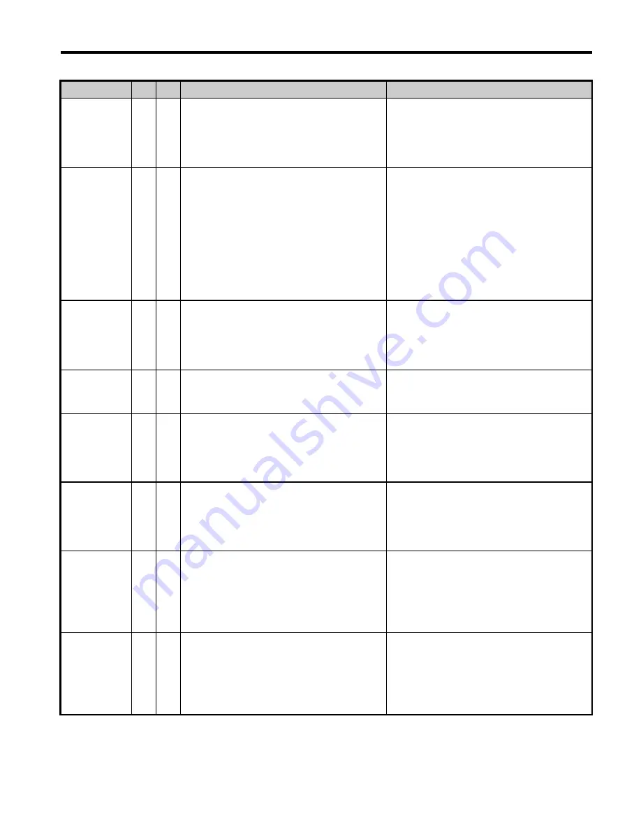
Output Phase
Loss
• Output cable is disconnected or the motor
winding is damaged.
• Drive output wires are loose.
• Motor is too small (less than 5% of drive
current).
• Check the power supply.
• Make sure that all cables are properly con-
nected to the correct terminals.
Overcurrent
• Short-circuit or ground fault on the drive
output side.
• The load is too heavy.
• The acceleration or deceleration ramps are
too short.
• Incorrect motor data or V/f pattern settings.
• The motor contactor was switched while
the drive was running.
• Check the output wiring and the motor for
short circuits or broken insulation. Replace
the broken parts.
• Check the machine for damages (gears,
etc.) and repair any broken parts.
• Make sure the brake fully opens.
• Check accel/decel settings in C1-
and
C2-
.
• Check V/f pattern settings in E1-
.
• Check the output contactor sequence.
Encoder
Communicatio
n Data Error
• Encoder power supply voltage wrong.
• Wrong encoder type.
• Wrong wiring.
• Check the encoder power supply setting on
the option card.
• Check the encoder wiring, especially the
serial signal wires.
Encoder Error
• Noise on the encoder signal.
• Bad wiring.
• Check the encoder wiring and make sure
the encoder cable shield is properly
grounded.
Heatsink
Overheat
• Surrounding temperature is too high.
• The cooling fan has stopped.
• The heatsink is dirty.
• The airflow to the heatsink is restricted.
• Check the surrounding temperature and
install cooling devices if necessary.
• Check the drive cooling fan.
• Clean the heatsink.
• Check the airflow around the heatsink.
Motor
Overload
• The motor load is too heavy.
• Acceleration and deceleration cycle times
are too short.
• Value set for the motor rated current is
incorrect.
• Check the elevator mechanics.
• Check the sequence.
• Check the rated current setting.
Drive
Overload
• The load is too heavy.
• The drive is too small.
• Too much torque at low speed.
• Check the load.
• Make sure that the drive is big enough to
handle the load.
• The overload capability is reduced at low
speeds. Reduce the load or increase the
drive size.
DC
Overvoltage
• DC bus voltage rose too high.
• Braking transistor is too small
• Braking chopper or resistor is broken.
• Unstable motor control in OLV.
• Input voltage is too high.
• Make sure the braking resistor and braking
chopper are working correctly.
• Check motor parameter settings and adjust
torque and slip compensation as needed.
• Make sure that the power supply voltage
meets the drives specifications.
LED Display AL FLT
Possible Cause
Corrective Action
LF
oC
oFx53
oFx54
oH or oH1
oL1
oL2
ov


