background image

B  Parameter Table

190


YASKAWA

 TOEPYAIL1E01A YASKAWA AC Drive L1000E Quick Start Guide

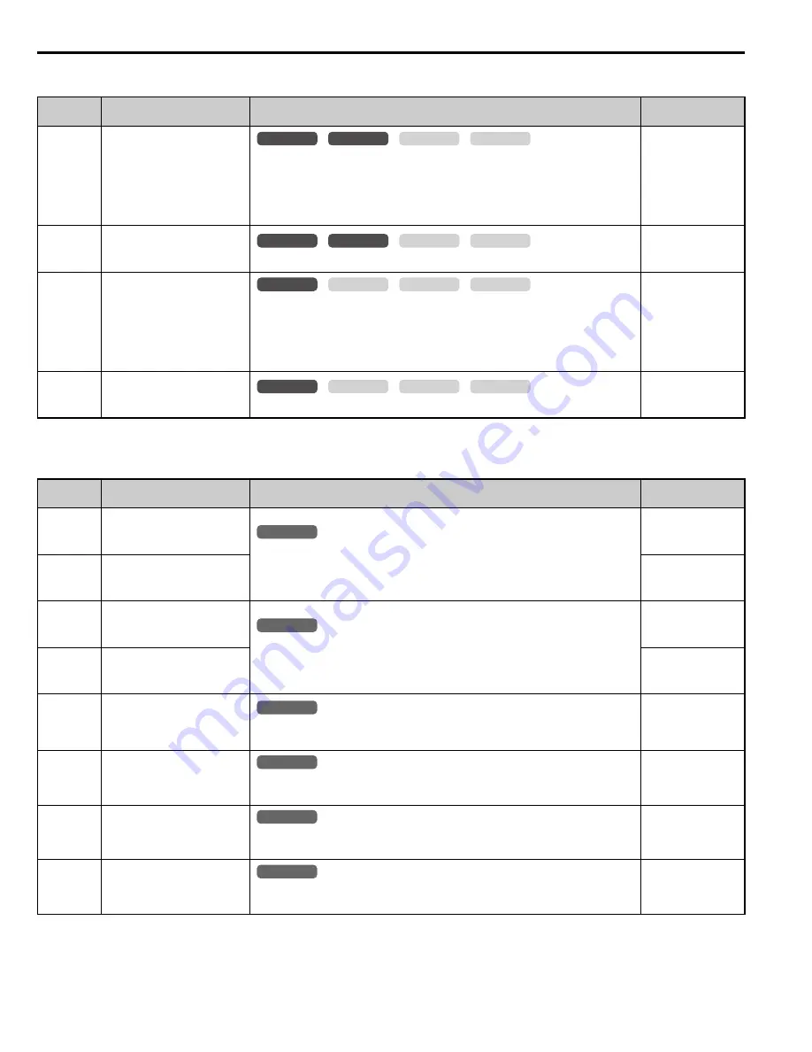
L3: Stall Prevention

L4: Speed Detection

No. 

(Addr.)

Name

Description

Setting

L3-01

(48FH)

<16> The setting value is dependent on the setting for the carrier frequency reduction (L8-38).

Stall Prevention Selection 
during Acceleration

0: Disabled.
1: General purpose. Acceleration is paused as long as the current is above the 
L3-02 setting. 
2: Intelligent. Accelerate in the shortest possible time without exceeding the L3-
02 level.

Default: 1
Min: 0
Max: 2

L3-02

(490H)

Stall Prevention Level during 
Acceleration

Used when L3-01 = 1 or 2. 100% is equal to the drive rated current.

Default: 

<16>

Min: 0%
Max: 150%

<16>

L3-05

(493H)

Stall Prevention Selection 
during Run

0: Disabled. Drive runs at a set frequency. A heavy load may cause speed loss.
1: Decel time 1. Uses the deceleration ramp set to C1-02 while Stall Prevention 
is performed.
2: Decel time 2. Uses the deceleration ramp set to C1-04 while Stall Prevention 
is performed.

Default: 1
Min: 0
Max: 2

L3-06

(494H)

Stall Prevention Level during 
Run

Enabled when L3-05 is set to 1 or 2. 100% is equal to the drive rated current.

Default: 

<16>

Min: 30%
Max: 150%

<16>

No. 

(Addr.)

Name

Description

Setting

L4-01

(499H)

Speed Agreement Detection 
Level

L4-01 sets the speed detection level for digital output functions H2-

 = 3, 4, 

5.
L4-02 sets the hysteresis or allowable margin for speed detection.

Default: 0.0%
Min: 0.0%
Max: 100.0%

L4-02

(49AH)

Speed Agreement Detection 
Width

Default: 4.0%
Min: 0.0%
Max: 40.0%

L4-03

(49BH)

Speed Agreement Detection 
Level (+/-)

L4-03 sets the speed detection level for digital output functions H2-

 = 13, 

14, 15, 16.
L4-04 sets the hysteresis or allowable margin for speed detection.

Default: 0.0%
Min: –100.0%
Max: 100.0%

L4-04

(49CH)

Speed Agreement Detection 
Width (+/-)

Default: 4.0%
Min: 0.0%
Max: 40.0%

L4-05

(49DH)

Speed Reference Loss 
Detection Selection

0: Stop. Drive stops when the speed reference is lost.
1: Run. Drive runs at a reduced speed when the speed reference is lost.

Default: 0
Min: 0
Max: 1

L4-06

(4C2H)

Speed Reference at 
Reference Loss

Sets the percentage of the speed reference that the drive should run with when 
the speed reference is lost.

Default: 80%
Min: 0.0%
Max: 100.0%

L4-07

(470H)

Speed Agree Detection Selection

0: No detection during baseblock
1: Detection always enabled

Default: 0
Min: 0
Max: 1

L4-13

(4F6H)

Door Zone Level

Sets the door zone speed level. The "door zone" multi-function digital output is 
closed when the speed falls below this level.

Default: 0.0%
Min: 0.0%
Max: 100.0%

common

_

CLV

CLV/PM

V/f

OLV

common

_

CLV

CLV/PM

V/f

OLV

common

_

CLV

CLV/PM

V/f

OLV

common

_

CLV

CLV/PM

V/f

OLV

All Modes

common

_

All Modes

common

_

All Modes

common

_

All Modes

common

_

All Modes

common

_

All Modes

common

_

Summary of Contents for L1000E

Page 1: ...intenance Ensure the end user receives this manual Type CIMR LE A Receiving Mechanical Installation Electrical Installation Start Up Programming Operation Option Card Installation Troubleshooting Periodic Inspection Maintenance Specifications Parameter Table Standards Compliance 1 2 3 4 6 5 7 A B C PW R LE D MON ITOR JVOP 184 RU N DS 1 DS 2 RU N DS1 DS2 ST AT US RE AD Y RU N AL AR M RUN PG OH LT B...

Page 2: ...en permission of Yaskawa No patent liability is assumed with respect to the use of the information contained herein Moreover because Yaskawa is constantly striving to improve its high quality products the information contained in this manual is subject to change without notice Every precaution has been taken in the preparation of this manual Nevertheless Yaskawa assumes no responsibility for error...

Page 3: ...rm Auto Tuning Automatic tuning sets motor parameters Refer to Types of Auto Tuning on page 68 Maintenance Check Using Drive Monitors Use drive monitors to check fans capacitors and other components may require maintenance Refer to Performance Life Monitors Maintenance Monitors on page 144 Fault Display and Troubleshooting Refer to Troubleshooting on page 130 Standards Compliance Refer to UL Stand...

Page 4: ...4 YASKAWA TOEPYAIL1E01A YASKAWA AC Drive L1000E Quick Start Guide ...

Page 5: ...nnect to a PC 50 Wiring Checklist 51 4 Start Up Programming 52 LED Monitor JVOP 184 52 Digital Operator JVOP 180 Keys and Displays 53 The Drive and Programming Modes 58 Start Up Flowcharts 61 Setup Procedure for Elevator Applications 77 S Elevator Parameters 88 Setup Troubleshooting and Possible Solutions 123 5 Troubleshooting 130 Fault Detection 130 Alarm Detection 134 Operator Programming Errors...

Page 6: ...Phase 400 V Class Drives 160 Drive Specifications 161 B Parameter Table 163 Understanding the Parameter Table 163 Parameter Table 163 Defaults and Setting Ranges by Display Unit Selection o1 03 217 C Standards Compliance 219 UL Standards 219 Safe Disable Input Function 230 EN81 1 Compliant Circuit with one Motor Contactor 233 Revision History 234 ...

Page 7: ... jumper configuration basic troubleshooting standards compliance and fusing drive specifications and an abbreviated parameter list L1000E Series AC Drive Technical Manual This manual provides detailed information on parameter settings drive functions and MEMOBUS Modbus specifications Use this manual to expand drive functionality and to take advantage of higher performance features General Precauti...

Page 8: ...systems DANGER Indicates a hazardous situation which if not avoided will result in death or serious injury WARNING Indicates a hazardous situation which if not avoided could result in death or serious injury CAUTION Indicates a hazardous situation which if not avoided could result in minor or moderate injury NOTICE Indicates a property damage message DANGER Heed the safety messages in this manual ...

Page 9: ...uipment with covers removed Failure to comply could result in death or serious injury The diagrams in this section may show drives without covers or safety shields to show details Be sure to reinstall covers or shields before operating the drives and run the drives according to the instructions described in this manual When a drive is running a PM motor voltage continues to be generated at the mot...

Page 10: ...nd maintenance of AC drives Fire Hazard Drive Short Circuit Current Rating Install adequate branch circuit protection according to applicable local codes and this Installation Manual Failure to comply could result in fire and damage to the drive or injury to personnel The device is suitable for use on a circuit capable of delivering not more than 100 000 RMS symmetrical amperes 240 Vac maximum 200...

Page 11: ...ve high current will shorten the life span of the IGBTs Yaskawa recommends lowering the carrier frequency particularly when audible noise is not a concern It is beneficial to reduce the load increase the acceleration and deceleration times or switch to a larger drive to help keep peak current levels under 133 Be sure to check the peak current levels when starting and stopping repeatedly during the...

Page 12: ...ny external equipment such as braking resistors Failure to comply may cause resistor overheating fire and injury to personnel To get the full performance life out of the electrolytic capacitors and circuit relays refrain from switching the drive power supply off and on more than once every 30 minutes Frequent use can damage the drive Use the drive to stop and start the motor Inspection and Mainten...

Page 13: ...tion Vibration and Shock The drive allows selection of high carrier PWM control and low carrier PWM control Selecting high carrier PWM can help reduce motor oscillation If resonance occurs install shock absorbing rubber mounts around the base of the motor and utilize the Jump frequency selection to prevent continuous operation in the resonant frequency ranges Audible Noise Noise created during run...

Page 14: ...etween the drive and motor please wait 5 minutes before inspecting performing maintenance or wiring the drive Risk of electric shock Hot surfaces Top and Side surfaces may become hot Do not touch Warning Label CIMR LE2A0012FAA 200V 3Phase 5 5kW 3 7kW S N 危 険 据え付け 運転の前には必ず取扱説明書を読むこと 通電中および電源遮断後5分以内はフロントカバー を外さない事 400V級インバータの場合は 電源の中性点が接地 されていることを確認すること 対応 保守 点検 配線を行う場合は 出力側開閉器を 遮断後5分待って実施してください けが ...

Page 15: ...ion Quick Start Guide Quantity 1 1 1 PWR LED MONIT OR JVOP 1 84 RUN DS1 DS2 RUN DS1 DS2 STATU S READ Y RUN ALARM RUN PGOH LT BB HB B EF SE Other Fault OV UV OH O L OC GF SC PG O CPF O FA OF B OFC LIGH T BLIN K LIGH T OFF YEA_c o m Quick Start Guide PWR LED MON ITOR JVOP 184 RUN DS1 DS2 RUN DS1 DS2 STA TUS REA DY RUN ALA RM RUN PGO H LT BB H BB EF S E Oth er Fau lt OV UV OH OL OC GF S C PG O CPF OF...

Page 16: ...0 0 58 8 4A0030 15 0 20 0 30 0 2A0075 18 5 25 0 75 0 4A0039 18 5 25 0 38 8 2A0094 22 0 30 0 93 8 4A0049 22 0 30 0 48 8 2A0106 30 0 40 0 106 3 4A0056 30 0 40 0 56 3 2A0144 37 0 50 0 143 8 4A0075 37 0 50 0 75 0 2A0181 45 0 60 0 181 3 4A0094 45 0 60 0 93 8 2A0225 55 0 75 0 225 0 4A0114 55 0 75 0 113 8 2A0269 75 0 100 0 268 8 4A0140 75 0 100 0 140 0 2A0354 90 0 125 0 353 8 4A0188 90 0 125 0 187 5 2A04...

Page 17: ...er over the top of the drive during installation Remove the temporary cover before startup as the cover will reduce ventilation and cause the drive to overheat Environment Conditions Installation Area Indoors Ambient Temperature IP00 enclosure with top protective cover 10 to 40 C 14 to 104 F IP00 enclosure 10 to 50 C 14 to 122 F Drive reliability improves in environments without wide temperature f...

Page 18: ...7 for details on installing the drive Figure 5 Figure 4 Correct Installation Orientation Installation Spacing Figure 5 shows the installation distance required to maintain sufficient space for airflow and wiring Figure 6 Figure 5 Correct Installation Spacing A 50 mm 1 97 in minimum C 120 mm 4 72 in minimum B 30 mm 1 18 in minimum D Airflow direction A A B B Side Clearance Top Bottom Clearance C C ...

Page 19: ...bject the drive to vibration or impact greater than 1 96 m s2 0 2 G while it is suspended by the wires Do not overturn the drive while it is suspended by the wires Do not leave the drive suspended by the wires for long periods of time Horizontal Suspension of the Drive CIMR LE2A0432 and 4A0260 To make a wire hanger or frame for use when lifting the drive with a crane lay the drive in a horizontal ...

Page 20: ...0 79 3 10 5 0 20 M6 8 7 19 2 2A0094 221 8 70 351 13 80 198 7 80 193 7 60 335 13 20 8 0 30 79 3 10 5 0 20 M6 9 7 21 4 2A0106 2 249 9 80 399 15 70 259 10 20 196 7 70 386 15 20 8 0 30 99 3 90 25 0 10 25 0 10 M6 21 0 46 3 2A0144 274 10 80 450 17 70 259 10 20 221 8 70 434 17 10 8 0 30 99 3 90 25 0 10 25 0 10 M6 25 0 55 1 2A0181 325 12 80 551 21 70 284 11 10 259 10 20 536 21 10 8 0 30 109 4 30 25 0 10 2...

Page 21: ... 284 11 20 8 0 30 56 2 20 5 0 20 M5 5 4 11 9 4A0039 180 7 10 300 11 80 188 7 40 160 6 30 284 11 20 8 0 30 76 3 00 5 0 20 M5 5 4 11 9 4A0049 221 8 70 351 13 80 198 7 80 193 7 60 335 13 20 8 0 30 79 3 10 5 0 20 M6 8 0 18 3 4A0056 2 249 9 80 399 15 70 259 10 20 196 7 70 386 15 20 8 0 30 99 3 90 3 0 10 3 0 10 M6 22 0 46 3 4A0075 274 10 80 450 17 70 259 10 20 221 8 70 434 17 10 8 0 30 99 3 90 3 0 10 3 ...

Page 22: ... 0 10 M10 80 176 4 2A0432 500 19 70 800 31 50 330 13 00 371 14 60 772 30 40 13 0 50 130 5 10 5 0 20 5 0 20 M12 98 216 1 Drive Model Figure Dimensions mm in Weight kg lbs W H D W1 H1 H2 D1 t1 t2 d 4A0225 1 450 17 70 706 27 80 330 13 00 325 12 80 681 26 80 13 0 50 130 5 10 3 0 10 3 0 10 M10 79 174 2 4A0260 500 19 70 800 31 50 330 13 00 371 14 60 772 30 40 13 0 50 130 5 10 5 0 20 5 0 20 M12 96 211 6 ...

Page 23: ...wiring terminals U T1 V T2 W T3 3 2 1 B1 B2 from all other wiring Place motor wiring within its own conduit or cable tray with appropriate divider and use shielded motor cable where appropriate Improper wiring practices could result in malfunction of drive due to electrical interference NOTICE Inadequate wiring could result in damage to the drive Install adequate branch circuit short circuit prote...

Page 24: ...al relay option U X S1 S2 S3 S4 S5 S6 S7 A1 A2 0 V AC R R S S IG Drive B1 1 2 B2 2 kΩ S8 SC 0 V FM AM AC E G 1 8 8 9 2 3 24 V V MA M1 M2 MB MC Jumper Braking resistor option Up command Stop External Fault Fault Reset Multi step Speed 1 Not Used Multi function digtial inputs default setting Sink Source mode selection wire jumper default Sink Multi function analog inputs Power supply 10 5 Vdc max 20...

Page 25: ...or instructions 11 Disconnect the wire jumper between H1 HC and H2 HC when utilizing the Safe Disable input 12 Monitor outputs work with devices such as analog frequency meters ammeters voltmeters and wattmeters They are not intended for use as a feedback type of signal 13 When the drive is set to trigger a fault output upon activation of the fault reset function L5 02 1 a sequence to interrupt po...

Page 26: ... own conduit or cable tray with appropriate divider and use shielded motor cable where appropriate Improper wiring practices could result in malfunction of drive due to electrical interference Figure 9 Drive Main Circuit Configurations 2A0018 to 2A0094 4A0009 to 4A0049 2A0106 and 2A0144 4A00456 and 4A0075 2A0181 and 2A0225 4A0094 to 4A0140 2A0269 to 2A0432 4A0188 to 4A0260 1 2 R L1 S L2 T L3 Relay...

Page 27: ... Figure 10 Figure 10 Removing the Terminal Cover 2 Push in on the tab located on the bottom of the terminal cover and gently pull forward to remove the terminal cover Figure 11 Figure 11 Removing the Terminal Cover Models 2A0106 to 2A0432 and 4A0056 to 4A0260 1 Loosen the screws on the terminal cover then pull down on the cover CAUTION Do not completely remove the cover screws just loosen them If ...

Page 28: ... and use shielded motor cable where appropriate Improper wiring practices could result in malfunction of drive due to electrical interference Reattach the terminal cover after completing the wiring to the drive and other devices Figure 14 Figure 14 Reattaching the Terminal Cover Models 2A0106 to 2A0432 and 4A0056 to 4A0260 After wiring the terminal board and other devices double check connections ...

Page 29: ...e of the LED monitor until it clicks into place Figure 17 Figure 17 Reattaching the LED Monitor Removing Reattaching the Front Cover Removing the Front Cover Models 2A0018 to 2A0094 and 4A0009 to 4A0049 After removing the terminal cover and the LED monitor loosen the screw that affixes the front cover models 2A0059 4A0030 and 4A0039 do not use a screw to affix the front cover Pinch inwards on the ...

Page 30: ...the left side of the front cover then swing the left side towards you as shown in Figure 20 until the cover comes off Figure 20 Figure 20 Remove the Front Cover Models 2A0106 to 2A0432 and 4A0056 to 4A0260 Reattaching the Front Cover Models 2A0018 to 2A0094 and 4A0009 to 4A0049 Reverse the instructions given in Remove the Front Cover Models 2A0018 to 2A0094 and 4A0009 to 4A0049 on page 29 to reatt...

Page 31: ...l Installation 3 Models 2A0018 to 2A0094 and 4A0009 to 4A0049 1 Slide the front cover so the hooks on the top connect to the drive Figure 21 Figure 21 Reattach the Front Cover 2A0106 to 2A0432 and 4A0056 to 4A0260 2 After connecting the hooks to the drive press firmly on the cover to lock it into place ...

Page 32: ...der the ends of wire connections to the drive Soldered wiring connections can loosen over time Improper wiring practices could result in drive malfunction due to loose terminal connections NOTICE Do not switch the drive input to start or stop the motor Frequently switching the drive on and off shortens the life of the DC bus charge circuit and the DC bus capacitors and can cause premature drive fa...

Page 33: ...following formula to calculate the amount of voltage drop Line drop voltage V wire resistance Ω km wire length m current A 10 3 Refer to instruction manual TOBP C720600 0 for braking transistor option or braking resistor option wire gauges Use terminal 1 and the negative terminal when connecting a regenerative converter or a regen unit Use terminal B1 and when installing the braking unit to the dr...

Page 34: ...1 2 to 1 5 10 6 to 13 3 U T1 V T2 W T3 6 0 10 2 5 to 6 0 14 to 10 1 2 4 0 to 6 0 12 to 10 B1 B2 2 5 to 6 0 14 to 10 6 0 10 4 0 to 6 0 12 to 10 2A0031 R L1 S L2 T L3 10 8 2 5 to 16 12 to 6 M4 1 2 to 1 5 10 6 to 13 3 U T1 V T2 W T3 10 8 2 5 to 16 12 to 6 1 2 6 0 to 16 10 to 6 B1 B2 4 0 to 6 0 12 to 10 10 8 6 0 to 10 10 to 8 M5 2 to 2 5 17 7 to 22 1 2A0041 R L1 S L2 T L3 16 6 2 5 to 16 12 to 6 M4 1 2...

Page 35: ...6 to 25 6 to 4 M6 4 to 6 35 4 to 53 1 2A0106 R L1 S L2 T L3 70 1 0 6 0 to 50 10 to 1 0 M8 9 to 11 79 7 to 97 4 U T1 V T2 W T3 70 1 0 6 0 to 50 10 to 1 0 1 35 to 50 2 to 1 0 B1 B2 16 to 50 6 to 1 0 16 6 16 to 25 6 to 4 2A0144 R L1 S L2 T L3 70 2 0 6 0 to 95 10 to 3 0 M10 18 to 23 159 to 204 U T1 V T2 W T3 95 3 0 6 0 to 95 10 to 3 0 1 50 to 70 1 0 to 3 0 B1 B2 25 to 70 4 to 2 0 25 4 25 4 M8 9 to 11 ...

Page 36: ... T2 W T3 95 2P 3 0 2P 95 to 150 3 0 to 300 1 95 to 150 3 0 to 300 3 35 to 150 2 to 300 M10 18 to 23 159 to 204 35 3 35 to 150 2 to 300 M12 32 to 40 283 to 354 2A0354 R L1 S L2 T L3 120 2P 4 0 2P 95 to 150 3 0 to 300 M12 32 to 40 283 to 354 U T1 V T2 W T3 120 2P 4 0 2P 95 to 150 3 0 to 300 1 95 to 150 3 0 to 300 3 95 to 150 3 0 to 300 M10 18 to 23 159 to 204 35 2 35 to 150 2 to 300 M12 32 to 40 283...

Page 37: ...5 10 6 to 13 3 U T1 V T2 W T3 2 5 14 2 5 to 6 0 14 to 10 1 2 2 5 to 6 0 14 to 10 B1 B2 2 5 to 6 0 14 to 10 6 0 10 2 5 to 6 0 14 to 10 4A0019 R L1 S L2 T L3 6 0 10 2 5 to 16 12 to 6 M4 1 2 to 1 5 10 6 to 13 3 U T1 V T2 W T3 6 0 10 2 5 to 16 12 to 6 1 2 4 0 to 16 12 to 6 B1 B2 4 0 to 6 0 12 to 10 6 0 10 2 5 to 6 0 14 to 10 M5 2 to 2 5 17 7 to 22 1 4A0023 R L1 S L2 T L3 6 0 10 2 5 to 16 12 to 6 M4 1 ...

Page 38: ...2 1 16 6 10 to 16 8 to 6 M6 4 to 6 35 4 to 53 1 4A0056 R L1 S L2 T L3 25 4 6 0 to 50 10 to 1 0 M8 9 to 11 79 7 to 97 4 U T1 V T2 W T3 25 4 6 0 to 50 10 to 1 0 1 16 to 35 6 to 1 B1 B2 10 to 16 8 to 4 16 6 10 to 16 8 to 6 4A0075 R L1 S L2 T L3 35 3 6 0 to 70 10 to 3 0 M8 9 to 11 79 7 to 97 4 U T1 V T2 W T3 35 3 6 0 to 70 10 to 3 0 1 25 to 35 4 to 1 B1 B2 16 to 25 6 to 3 16 6 16 to 25 6 4A0094 R L1 S...

Page 39: ... T1 V T2 W T3 70 2 0 50 to 95 1 0 to 4 0 1 50 to 95 1 0 to 4 0 3 25 to 95 3 to 4 0 25 4 25 4 4A0188 R L1 S L2 T L3 95 4 0 50 to 95 1 0 to 4 0 M10 18 to 23 159 to 204 U T1 V T2 W T3 95 4 0 50 to 95 1 0 to 4 0 1 35 to 95 1 to 4 0 3 50 to 95 1 0 to 4 0 25 4 25 to 35 4 to 2 4A0225 R L1 S L2 T L3 50 2P 1 2P 35 to 150 2 to 300 M10 18 to 23 159 to 204 U T1 V T2 W T3 70 2P 1 0 2P 35 to 150 2 to 300 1 50 t...

Page 40: ...proper wiring practices could result in malfunction of drive due to electrical interference NOTICE Equipment Hazard Comply with proper wiring practices The motor may run in reverse if the phase order is backward causing incorrect elevator direction movement and injury to personnel Connect motor input terminals U T1 V T2 and W T3 to drive output terminals U T1 V T2 and W T3 The phase order for the ...

Page 41: ...ning multiple motors calculate cable length as the total wiring distance to all connected motors Ground Wiring Follow the precautions to wire the ground for one drive or a series of drives WARNING Electrical Shock Hazard Always use a ground wire that complies with technical standards on electrical equipment and local installation regulations Minimize the length of the ground wire Improper equipmen...

Page 42: ...al outputs M1 to M6 multi function photocoupler outputs P1 C1 P2 C2 multi function analog inputs A1 A2 and multi function analog monitor output FM AM The default setting is listed next to each terminal in Figure 8 on page 24 NOTICE Equipment Hazard Improper equipment sequencing could shorten useful life of the electrolytic capacitors and circuit relays of the drive Refrain from switching an input ...

Page 43: ...ence 1 S6 Multi function input 4 Multi Step Speed Reference 2 S7 Multi function input 5 Multi Step Speed Reference 3 S8 Multi function input 6 Not used Digital Input Power Supply SC Multi function input common 24 Vdc 150 mA only when DI A3 is not used Use the wire jumper between terminals SC and SN or between SC and SP to select sinking or sourcing and to select the power supply 49 SN 0 V SP 24 Vd...

Page 44: ...inimum load 5 Vdc 10 mA MB N C output MC Fault output common Multi Function Relay Output 1 M1 Multi function relay output 1 Brake release command Contact relay output 30 Vdc 10 mA to 1 A 250 Vac 10 mA to 1 A Minimum load 5 Vdc 10 mA M2 M3 Multi function relay output 2 Output contactor close command M4 M5 Multi function relay output 3 Drive ready M6 Multi Function Photocoupler Output P1 Photocouple...

Page 45: ...e wire type and gauges from Table 14 For simpler and more reliable wiring use crimp ferrules on the wire ends Refer to Table 15 for ferrule terminal types and sizes Table 14 Wire Gauges and Torque Specifications Terminal Block Terminal Size Tightening Torque N m lb in Bare Wire Terminal Ferrule Type Terminal Applicable Wire Size mm2 AWG Recomm mm2 AWG Applicable Wire Size mm2 AWG Recomm mm2 AWG Wi...

Page 46: ...ape to prevent contact with other signal lines and equipment Improper wiring practices could result in drive or equipment malfunction due to short circuit NOTICE Equipment Hazard Use twisted pair or shielded twisted pair cables for control circuits Improper wiring practices could result in drive or equipment malfunction or nuisance trips NOTICE Connect the shield of shielded cable to the appropria...

Page 47: ...nterference Connect control wires as shown in Figure 27 Figure 27 Figure 27 Terminal Board Wiring Guide When connecting control wires to the terminals use shielded twisted pair wires treating wire ends as shown in Figure 28 and connect the shield to the ground terminal E G of the drive Figure 28 Figure 28 Preparing the Ends of Shielded Cables NOTICE Do not exceed 50 meters 164 ft for the control l...

Page 48: ...several switches used to adapt the drive I Os to the external control signals Figure 29 shows the location of these switches Refer to Control I O Configuration on page 49 for setting instructions Figure 29 Figure 29 Locations of Jumpers and Switches on the Terminal Board Off On Jumper S3 Terminal H1 H2 Sink Source Sel DIP Switch S2 RS 422 485 Termination Resistor YEA_ com ...

Page 49: ...nal power supply for the digital inputs S1 to S8 as shown in Table 16 Default Sink mode internal power supply NOTICE Damage to Equipment Do not short terminals SP and SN Failure to comply will damage the drive Table 16 Digital Input Sink Source External Power Supply Selection Drive Internal Power Supply Terminal SN and SP External 24 Vdc Power Supply Sinking Mode NPN Sourcing Mode PNP SC S8 S7 24 ...

Page 50: ...ately After connecting the drive to a PC Yaskawa DriveWizard Plus software can be used to monitor drive performance and manage parameter settings Contact Yaskawa for more information on DriveWizard Plus Download and install the USB driver before connecting L1000 to a PC with the USB cable To obtain the driver and software of USB Copy Unit CopyUnitManager and DriveWizardPlus access these sites U S ...

Page 51: ...selecting wire gauges Increase the wire gauge when the voltage drop is greater than 2 of motor rated voltage Ensure the wire gauge is suitable for the terminal block Use the following formula to calculate the amount of voltage drop Line drop voltage V 3 wire resistance Ω km wire length m current A 10 3 33 If the cable between the drive and motor exceeds 50 m 164 feet adjust the carrier frequency s...

Page 52: ... the drive is ready and no FWD REV signal is active Figure 32 Figure 32 Normal Operation LED Alarm Figure 33 shows the LED display when a minor fault occurs Refer to Troubleshooting on page 130 and take appropriate countermeasures Figure 33 Figure 33 Alarm LED Fault Figure 34 shows the LED display when an oV or UV fault has occurred Figure 34 Figure 34 Fault LED A PWR LED Red E DS2 LED Green B Dri...

Page 53: ... or when the speed reference is 0 flashes quickly the drive is disabled by a DI the drive was stopped using a fast stop DI or an Up Down command was active during power up 5 Up Arrow Key Scrolls up to display the next item select parameter numbers and increment setting values 6 Down Arrow Key Scrolls down to display the previous item select parameter numbers and decrements setting values 7 STOP Ke...

Page 54: ...splayed when in Drive Mode PRG Displayed when in Programming Mode 3 Ready Rdy Indicates the drive is ready to run 4 Data Display Displays specific data and operation data 5 Speed Reference Source Assignment 1 OPR Displayed when the speed reference source is assigned to the LCD Operator COM Displayed when the speed reference source is assigned to MEMOBUS Modbus Communication OP Displayed when the s...

Page 55: ...ault or error 1 Displayed when in Drive Mode 2 Displayed when in Drive Mode and Monitor Mode Power off Checks Description Power supply voltage Ensure the power supply voltage is correct on the supply side of the disconnect before applying power to the drive 200 V class 3 phase 200 to 240 Vac 50 60 Hz 400 V class 3 phase 380 to 480 Vac 50 60 Hz Properly wire the power supply input terminals R L1 S ...

Page 56: ...n flashing and flashing quickly Off When source of the Up Down command is assigned to the digital operator LOCAL Up Down command to be given from a device other than the digital operator REMOTE During run During deceleration to stop When an Up Down command is input and speed reference is 0 While the drive is set for LOCAL an Up Down command was entered to the input terminals after which the drive ...

Page 57: ...ed setting OFF ON Flashing OFF OFF RUN LED RUN 0 10 RUN STOP STOP Up Down common_ TM MODE U1 01 0 00 U1 02 0 00 U1 03 0 00A DRV Speed Ref OPR Rdy MONITR Speed Ref 1 U1 01 000 00 3 4 㸦0 00㹼50 00㸧 0 00 DRV FWD Rdy MODE U1 01 0 00 U1 02 0 00 U1 03 0 00A DRV Monitor Menu Rdy MODE PRG Modified Consts HELP HELP DATA MODE PRG Quick Setting DATA HELP MODE PRG Rdy Auto Tuning DATA HELP MODE PRG DATA Progra...

Page 58: ...o the drive The initial display appears 2 Press or until the Parameter Setting Mode screen appears 3 Press to enter the parameter menu tree 4 Press or to select the C parameter group 5 Press two times 6 Press or to select the parameter C1 02 7 Press to view the current setting value 1 5 s The left most digit flashes 8 Press or until the desired number is selected 1 flashes 9 Press and enter 0020 0...

Page 59: ...m the change 11 The display automatically returns to the screen shown in Step 4 12 Press as many times as necessary to return to the initial display Step Display Result Entry Accepted φ ψ PRMSET C1 02 2 50 sec 0 0 600 00 1 50 sec PRG Decel Ramp 1 FWD MODE U1 01 0 00 U1 02 0 00 U1 03 0 00A DRV Speed Ref OPR Rdy RSEQ LREF FWD FWD REV ...

Page 60: ...ccessed to change b1 01 from 0 to 1 This changes the source of the speed reference from the digital operator to the control circuit terminals Figure 40 Setup Group Example 1 Use the up and down arrow keys to scroll through the Setup Group Press the ENTER key to view or change parameter settings 2 To return to the previous menu without saving changes press the ESC key MODE U1 01 0 00 U1 02 0 00 U1 ...

Page 61: ...n the Digital Operator Start Up Flowcharts This section covers basic setup for the drive including Auto Tuning procedures and corresponding flowcharts Follow the flowchart that matches the motor used in your application Refer to Types of Auto Tuning on page 68 for details on the types of Auto Tuning Step Display Result 1 Turn on the power to the drive The initial display appears 2 Press The LO RE ...

Page 62: ... Digital operator b1 01 0 Speed selection by digital inputs Assign functions to the analog digital I O terminals using parameters H1 H2 H3 and H4 Set up Acceleration deceleration ramp C1 Jerk settings C2 Perform a test run Fine tuning Adjust settings for the brake sequence S1 Adjust speed control loop C5 etc FINISH Set up Preset speed references d1 Acceleration deceleration ramp C1 Jerk settings C...

Page 63: ...he correct state WARNING Sudden Movement Hazard Operating a drive with untested emergency circuits could result in death or serious injury Always check the operation of drive fast stop circuits and any additional emergency circuits after they are wired Fast stop circuits are required to provide safe and quick shutdown of the drive NOTICE Equipment Hazard Comply with proper wiring practices The mot...

Page 64: ...LED will extinguish when the DC bus voltage is below 50 Vdc To prevent electric shock wait at least five minutes after all indicators are OFF and measure the DC bus voltage level to confirm safe level Note Always perform motor rotation direction setup prior to setting the encoder rotation direction PG Encoder Setup PG Encoder Resolution Setup Set the encoder resolution incremental signal in the ca...

Page 65: ...tate freely Select Stationary Auto Tuning for Terminal Resistance only T1 01 2 Select Stationary Auto Tuning 1 or 2 T1 01 1 or 4 No A1 02 2 or 3 Yes A1 02 0 No Yes Ropes removed Select Rotational Auto Tuning T1 01 0 Press the Up key until Tuning Ready is displayed Enter the data in to T1 parameters as indicated on the display Press the Up key until Tuning Ready is displayed 1 Release the Brake Clo...

Page 66: ... input H1 8 9 if used Tuning Successful Refer to Remove the Fault Alarm source and repeat Auto Tuning Open terminals H1 HC and H2 HC if used during the normal sequence Open the motor contactor s Open the Baseblock input H1 8 9 if used No Alarm or Fault code displayed Yes Entry Accepted displayed 2 Enter the data in to T2 parameters as indicated on the display Select Motor Data Input T2 01 0 Enter ...

Page 67: ...uning possible Select Stationary Encoder Offset Auto Tuning T2 01 4 Press the Run key on the digital operator and wait until Auto Tuning is finished Set terminals H1 HC and H2 HC if Safe Disable function is used Set the Baseblock input H1 8 9 if used Close the motor contactor s Press the Up key until Tuning Ready is displayed Select Rotational PG Encoder Offset Auto Tuning T2 01 10 Press the Run k...

Page 68: ...less then with Rotational Auto Tuning No Yes Yes Stationary Auto Tuning for Line to Line Resistance T1 01 2 Used for V f Control or in vector control modes when the drive was previously set up properly and now the motor cable has changed Used in V f control if drive and motor capacities differ Should not be used for any vector control modes unless the motor cable has changed Yes Yes Yes Stationary...

Page 69: ... Axis Inductance T2 12 mH Yes N A N A N A N A N A N A N A Induced Voltage Constant Unit Selection T2 13 N A Yes N A N A N A N A N A N A N A Voltage Constant T2 14 1 Yes N A N A N A N A N A N A N A PG Number of Pulses per Revolution T2 16 N A Yes Yes N A N A N A N A N A N A Z Pulse Offset T2 17 deg mech Yes N A N A N A N A N A N A N A Speed Reference for Auto Tuning of PG E3 Encoder Characteristics...

Page 70: ...will be interrupted and a fault code will appear on the digital operator Figure 41 Figure 45 Auto Tuning Aborted Display Auto Tuning Operation Example The following example demonstrates Rotational Auto Tuning when using OLV A1 02 2 Selecting the Type of Auto Tuning Enter Data from the Motor Nameplate After selecting the type of Auto Tuning enter the data required from the motor nameplate Step Disp...

Page 71: ...y in Step 1 6 Repeat Steps 1 through 5 to set the following parameters T1 03 Motor Rated Voltage T1 04 Motor Rated Current T1 05 Motor Base Frequency T1 06 Number of Motor Poles T1 07 Motor Base Speed A TUNE T1 02 3 70kW 0 00 650 00 PRG Mtr Rated Power ESC FWD DATA 3 70kW A TUNE T1 02 003 70kW 0 00 650 00 PRG Mtr Rated Power FWD 3 70kW F1 left F2 right A TUNE T1 02 004 00kW 0 00 650 00 PRG Mtr Rat...

Page 72: ... Induction Motor Auto Tuning T1 The T1 parameters are used to set the Auto Tuning input data for induction motor tuning Note For motors operating in the field weakening range first perform the Auto Tuning with the base data After Auto Tuning is complete change E1 04 Maximum Output Frequency to the desired value T1 01 Auto Tuning Mode Selection Sets the type of Auto Tuning to be used Refer to Auto ...

Page 73: ... range is used or if the motor is used in the field weakening area enter the maximum frequency to E1 04 E3 04 for motor 2 after Auto Tuning is complete T1 06 Number of Motor Poles Sets the number of motor poles according to the motor nameplate value T1 07 Motor Base Speed Sets the motor rated speed according to the motor nameplate value If a motor with an extended speed range is used or if the mot...

Page 74: ... 4 Stationary PG Encoder Offset Auto Tuning Setting 10 Rotational PG Encoder Offset Auto Tuning Setting 11 Rotational Back EMF Constant Auto Tuning Setting 12 Auto Tuning of PG E3 Encoder Characteristics T2 04 PM Motor Rated Power Specifies the PM motor rated power in kilowatts T2 05 PM Motor Rated Voltage Sets the PM motor rated voltage No 1 The display resolution depends on the rated output powe...

Page 75: ...3 is set to 0 then the drive will use E5 24 Motor Induction Voltage Constant 2 and will automatically set E5 09 Motor Induction Voltage Constant 1 to 0 0 If T2 13 is set to 1 then the drive will use E5 09 and will automatically set E5 24 to 0 0 No Parameter Name Setting Range Default T2 06 PM Motor Rated Current 10 to 200 of the drive rated current Depending on o2 04 No 1 When PG E3 option connect...

Page 76: ...ng of PG E3 encoder characteristics T2 01 12 T2 19 Rotation Direction for Auto Tuning of PG E3 Encoder Characteristics Sets the direction of motor rotation for execution of Auto Tuning of PG E3 encoder characteristics T2 01 12 Setting 0 Forward Up Setting 1 Reverse Down No Parameter Name Setting Range Default T2 14 PM Motor Induced Voltage Constant 0 0 to 2000 0 Depending on T2 02 No Parameter Nam...

Page 77: ...wn command can be selected using parameter b1 02 Travel Start and Stop Travel Start To start the elevator in the up or down direction the following conditions must be fulfilled A speed reference greater than zero must be provided The Safe Disable signals at terminals H1 and H2 must both be closed drive output enabled If a multi function digital input is programmed for Baseblock H1 8 or 9 this inpu...

Page 78: ...or 3 Speed Selection When d1 18 0 or 3 multi function digital inputs are preset as shown below Different speed reference settings can be selected by combining the three digital inputs as shown in the table below Note Parameters d1 19 through d1 26 are displayed only if d1 18 is set to 1 or 2 d1 18 Speed Selection 0 default Multi speed inputs 1 Speed references are set in d1 01 to d1 08 1 Separate ...

Page 79: ...ough d1 26 are displayed only if d1 18 is set to 1 or 2 Higher Speed has Priority and the Leveling Speed Input is Assigned d1 18 1 and H1 53 Default The higher speed has priority over the leveling speed The leveling signal is disregarded as long as any other speed selection input is active The drive decelerates to the leveling speed d1 26 when the selected speed reference signal is removed Termina...

Page 80: ...NOTICE Equipment Hazard This function may not work properly if a broken wire connection to the drive I O causes improper elevator speed selection Properly tighten wire connections at the drive terminals before enabling this function Multi Function Terminal Setup Multi Function Digital Input Terminals S3 to S8 The H1 parameters assign functions to digital input terminals S3 to S8 digital input term...

Page 81: ...mergency Coast to Stop An emergency coast to stop is performed when the Up or Down command is cleared and all of the following conditions are met Parameter b1 03 Stopping Method Selection is set to 4 Parameter d1 18 Speed Reference Selection Mode is set to 0 or 3 Parameter b1 01 Speed Reference Selection is set to 1 The Up Down command is cleared and U1 05 Speed Feedback is equal to or greater tha...

Page 82: ...uence at start as normal operation The carrier frequency is set to 2 kHz during Inspection Operation but can be changed using parameter C6 21 Stop Condition in Inspection Operation To stop the drive during Inspection Operation either remove the Up or Down command or reset the input terminal for Inspection Operation A deceleration ramp can be set for Inspection Operation using parameter C1 15 If C1...

Page 83: ...n do not set any analog input terminals for Torque compensation H3 14 Figure 45 Figure 50 Brake Sequence without Torque Compensation at Start Figure 50 is divided into time zones 1 The drive stops if either the Up Down command or Inspection Operation signals are removed Inspection Operation Speed DC Injection Braking Position Lock at start DC Injection Braking Position Lock at start Speed Up Down ...

Page 84: ...50 in order to release the brake t3 DC Injection Braking or Position Lock will continue until the time S1 04 has elapsed or the time S1 06 has elapsed if S1 06 S1 04 this setting should be avoided since the motor could be driven against the applied brake t4 The drive accelerates up to the selected speed The speed is kept constant until the leveling speed is selected t5 Leveling speed is selected T...

Page 85: ...e feedback signal is on before the contactor control command has been issued an SE1 fault is triggered If the motor contactor feedback signal is not used then the drive waits for the operation start delay time set in S1 10 to pass then proceeds to the next step The drive reads the torque value from the analog input load cell t2 After the delay time set in S1 10 has passed the drive outputs current...

Page 86: ...ly load to the car has much as possible at least 50 of the maximum weight 3 Note the value of the analog input monitor for the load signal input connected to U1 13 for terminal A1 U1 14 for terminal A2 4 Provide an elevator Up or Down command using Inspection Operation or normal operation mode The car should be held in place when the brake releases 5 Note the drives internal torque reference monit...

Page 87: ...the settings of S3 12 and S3 27 through S3 30 Figure 48 Figure 53 Torque Compensation at Start for the Elevator in Up and Down Direction S3 30 S3 27 S3 28 Torque Compensation Value with Load Condition 2 Torque Compensation at Start for the Elevator in the Down Direction S3 29 Analog Input from Load Sensor with Load Condition 1 Torque Compensation Value with Load Condition 1 During Load Condition 2...

Page 88: ...nt to use for DC Injection at start Set as a percentage of the drive rated current S1 03 DC Injection Current at Stop Determines the amount of current to use for DC Injection at stop Set as a percentage of the drive rated current When using OLV Control the DC injection current is determined by multiplying S1 03 by S3 25 or S3 26 S1 04 DC Injection Position Lock Time at Start Determines how long th...

Page 89: ... and drive output has been shut off S1 12 Motor Contactor Control During Auto Tuning Selection Determines the state of the output contactor control command H2 51 during Auto Tuning The contactor closes as soon as the Enter key is pressed in the Auto Tuning start menu Setting 0 Disabled Setting 1 Enabled Setting 2 Enabled during Auto Tuning and HBB WARNING Sudden Movement Hazard Use parameter S1 12...

Page 90: ...tion Gain in Motoring Mode Regenerative Mode Slip compensation for leveling speed can be set separately for motoring and regenerative states to help improve the accuracy of leveling S2 05 Slip Compensation Torque Detection Delay Time Sets a delay time before detecting torque for slip compensation S2 06 Slip Compensation Torque Detection Filter Time Constant Sets the filter time constant applied to...

Page 91: ...nd car vibration Note 1 Check the C5 parameters to make sure the speed control loop settings are correct before making any adjustments to the Position Lock gain 2 Faults may occur when detecting the direction of motor rotation dv4 when using CLV PM To correct this either increase the settings of S3 01 and S3 02 or increase the number of pulses required to trigger dv4 F1 19 S3 04 Position Lock Band...

Page 92: ... function Note Setting this parameter to 0 00 disables the Dwell 2 function Figure 49 Figure 54 Dwell Speed Reference at Start S3 21 Dwell 2 End Speed The Dwell 2 function will end when the drive reaches this speed A setting of 0 00 will disable the acceleration rate switch that occurs at the end of Dwell 2 No Parameter Name Setting Range Default S3 14 Torque Compensation Diminish Speed 0 0 to 200...

Page 93: ...analog signal from a load sensor for torque compensation Refer to Adjusting the Torque Compensation at Start on page 85 for details S3 30 Analog Input from Load Sensor with Load Condition 2 Adjusts the analog signal from a load sensor for torque compensation Refer to Adjusting the Torque Compensation at Start on page 85 for details S3 34 Anti Rollback Torque Bias 1 Sets an intermediary value for t...

Page 94: ...already been adjusted Lower S3 39 if oscillation occurs This parameter rarely needs to be changed S3 40 Anti Rollback Movement Detection Sets the amount of speed feedback signal pulses to detect a movement of the rotor S3 41 Position Lock Gain at Start 2 Reduction Sets a reduction factor for the Position Lock Gain at Start 2 Anti Rollback Gain set in parameter S3 02 If the motor rotation i e car m...

Page 95: ...scue Operation Torque Limit Sets the torque limit used during Rescue Operation S4 06 Rescue Operation Power Supply Selection Specifies the type of backup power supply the drive should switch to when the power goes out Setting 0 Battery Setting 1 UPS single phase Setting 2 UPS three phase No Parameter Name Setting Range Default S4 01 Light Load Direction Search Selection 0 to 2 0 No Parameter Name ...

Page 96: ...PF5 fault is triggered The following conditions will trigger PF5 During Rescue Operation DC bus voltage S4 12 S4 13 10 100 ms after Rescue Operation has been triggered the DC bus voltage does not rise above S4 12 S4 13 before the motor starts S4 15 Speed Reference Selection at Rescue Operation Selects the speed reference used for Rescue Operation Setting 0 The setting of parameter d1 25 is used as...

Page 97: ...ce for a stop from nominal speed Figure 50 Figure 55 Speed During Normal Operation 1 The drive will recognize the speed reference that is lower than the Leveling Speed Detection Level d1 28 as the leveling speed if the speed priority is set for multi step speed reference d1 18 0 or 3 Advance Short Floor Advanced Short Floor minimizes the operation time to arrive at a designated floor It uses the l...

Page 98: ...ose The speed is 40 of the nominal speed or more d1 19 Nominal Speed d1 26 Leveling Speed H1 53 Leveling Speed 1 0 Operating speed Time 40 of nominal speed ON close The speed is over Optimum Speed d1 19 Nominal Speed Optimal Speed d1 26 Leveling Speed H1 53 Leveling Speed 1 Operating speed 0 ON close Time The speed is less than 40 of the nominal speed H1 53 Leveling Speed 1 d1 19 Nominal Speed d1 ...

Page 99: ...ncrease the gain level set to S5 04 and S5 05 if the leveling time is too short or if the optimum speed calculated by the drive is too fast Decrease the gain level set to S5 04 and S5 05 if the leveling time is too long or if the optimum speed calculated by the drive is too slow Note Setting S5 04 too low may trigger an overrun due to faster optimum speeds and shortened leveling times Avoid settin...

Page 100: ...s Droop Control b7 parameters Shoot Floor Advanced Short Floor S5 01 1 2 Leveling Distance Control is disabled when any one of the following functions are selected Analog frequency reference Rescue Operation Inspection Operation During Motor 2 selection Direct Landing Direct Landing S5 10 1 is activated at the start of deceleration and brings the elevator car to the designated floor without the us...

Page 101: ...Control Start Conditions Multi step speed sequence d1 18 0 3 The Up Down command is not active or the speed reference is 0 High speed reference has priority d1 18 1 Leveling speed reference is selected H1 53 The Up Down command is not active or all input terminals set for H1 50 to 53 are open Leveling speed reference is not selected H1 53 Up Down command is not active Multi step speed sequence d1 ...

Page 102: ...eling operation is complete to when the car arrives at the designated floor No Parameter Name Setting Range Default S5 10 Stopping Method Selection 0 to 2 0 No Parameter Name Setting Range Default S5 11 1 The setting range becomes 0 00 to 650 00 inches when the length units are set for inches o1 12 1 Deceleration Distance 0 to 32767 mm 1 0 mm No Parameter Name Setting Range Default S5 12 1 The set...

Page 103: ...en the Brake Control command is activated as a percentage of the Motor No load Current E2 03 A Starting Current Error SE2 occurs when the drive s output current is less than the value in S6 03 after both the Brake Release Delay Time S1 06 and the SE2 Detection Delay Time S6 02 have passed after a RUN command S6 04 Output Current Error SE3 Detection Delay Time Sets a delay time for detecting an out...

Page 104: ... 8 9 or from Safe Torque Off state Safe Disable inputs H1 and H2 enabled while the Up Down command is still active Setting 0 No restart after Baseblock or Safe Torque Off Do not restart the motor when leaving the Baseblock or Safe Torque Off state even if an Up Down command is still active Setting 1 Restart after Baseblock or Safe Torque Off Restart when the Up Down command is still active while t...

Page 105: ...When using a single phase AC power supply for rescue operation such as a single phase UPS the ripple in the DC bus voltage will be higher than with a three phase or battery supply Make sure that the DC bus voltage never falls below the minimum value listed in Table 30 When using a PM motor with an incremental PG encoder and a PG X3 option card always perform Initial Magnet Pole Search Parameters A...

Page 106: ...g the main power supply to a battery or UPS requires magnetic contactors that must be controlled by an external controller Wiring methods and the sequence used for the magnetic contactors depend on the application This instruction manual describes the following configurations A single phase 230 V UPS is used as backup power supply for a 200 V or 400 V class drive Two separate batteries for the mai...

Page 107: ... uses a low DC bus voltage which can cause the cooling fan to shut off temporarily during Rescue Operation Continuing to operate under these conditions can trigger an overheat fault and damage the drive NOTICE Install the inrush current suppression circuit outside the drive if the DC bus battery voltage is lower than 190 Vdc for 200 V class drives of models CIMR LE2A0269 to 2A0432 380 Vdc for 400 ...

Page 108: ...eration with normal power supply Application Precautions The drive may fault on a control power supply fault Uv2 if the UPS can t provide enough voltage or if the Light Load Direction Search is not set properly If this problem occurs take the following corrective actions Corrective Action Use a separate battery for the controller power supply Use a battery with a voltage higher than 250 Vdc for 20...

Page 109: ...ing Two Batteries for DC Bus and Control Power Supply DC Bus Battery is less than 250 V Operation Sequence Starting Rescue Operation 1 Open contactor B and wait at least 5 seconds 2 Set the input terminal programmed for Rescue Operation H1 55 3 Close contactors A and C 4 Set the Up Down command Ending Rescue Operation 1 After the car has stopped open contactors A and C 2 Clear the input terminal s...

Page 110: ...se the soft charge bypass relay to remain open and result in damage to the drive Current sensor R L1 S L2 T L3 1 U T1 V T2 W T3 Relay Power supply board Control board OPE CN19 A C B Battery for control circuit 200 V Class 250 to 340 Vdc 400 V Class 500 to 680 Vdc DC bus power supply H1 55 Rescue Operation L1 L2 L3 D 3 Battery for DC bus 200 V Class 48 to 190 Vdc 400 V Class 48 to 380 Vdc L1000A Af...

Page 111: ...ttery Voltage 1 Select the appropriate relay referring to the following calculation even if the battery voltage or main power current is applied Drive Model CIMR LE Resistor Relay 200 V 2A0269 1 0 Ω 80 W 1 2A0354 1 0 Ω 80 W 2A0432 1 0 Ω 80 W 400 V 4A0188 1 0 Ω 120 W 4A0225 1 0 Ω 220 W 4A0260 1 0 Ω 220 W Load current of battery A Motor rated power kW Operation frequency when running battery Hz 2 10...

Page 112: ...ensor R L1 S L2 T L3 1 3 U T1 V T2 W T3 Relay Power supply board Control board OPE CN19 A C B Battery for control circuit 200 V Class 250 to 340 Vdc 400 V Class 500 to 680 Vdc DC bus power supply H1 55 Rescue Operation L1 L2 L3 DC bus power supply 200 V Class 190 to 340 Vdc 400 V Class 380 to 680 Vdc L1000A S3 to S12 SC Magnetic Contactor Sequence Magnetic Contactor B Magnetic Contactor A Magnetic...

Page 113: ...e 62 Using a Battery for the DC Bus and 24 V Power Supply Unit Option for the Control Circuit Operation Sequence Starting Rescued Operation 1 Open contactor B and wait at least 5 seconds 2 Set the input terminal programmed for Rescue Operation H1 55 3 Close contactors A and C 4 Set the Up Down command Ending Rescue Operation 1 After the car has stopped open contactors A and C 2 Clear the input ter...

Page 114: ...rives and 380 Vdc for 400 V class drives Failure to comply will cause the soft charge bypass relay to remain open and result in damage to the drive Current sensor R L1 S L2 T L3 1 U T1 V T2 W T3 Relay Power supply board Control board OPE A B DC bus power supply H1 55 Rescue Operation L1 L2 L3 D 3 Battery for DC bus 200 V Class 48 to 190 Vdc 400 V Class 48 to 380 Vdc L1000A After the DC bus voltage...

Page 115: ...ives Current sensor R L1 S L2 T L3 1 3 U T1 V T2 W T3 Relay Power supply board Control board OPE A B DC bus power supply H1 55 Rescue Operation L1 L2 L3 DC bus power supply 200 V Class 190 to 340 Vdc 400 V Class 380 to 680 Vdc L1000A S3 to S12 SC Magnetic Contactor Sequence Magnetic Contactor B Magnetic Contactor A Magnetic Contactor C H1 55 Rescue Operation After the DC bus voltage falls lower th...

Page 116: ...peration 1 Open contactor B 2 Set the input terminal programmed for Rescue Operation H1 55 3 Close contactor A 4 Set the Up Down command Ending Rescue Operation 1 After the car has stopped open contactor A 2 Clear the input terminal set for Rescue Operation H1 55 3 Close contactor B to return to operation with normal power supply S3 to S8 L1000A DC bus power supply L1 L2 L3 CN19 1 4 W T3 V T2 U T1...

Page 117: ...and CIMR LE4A0009 to 4A0049 1 Insert the tip of a screwdriver into the opening on the edge of the CN19 connector cover Slide the cover off the drive as indicated in Figure 66 NOTICE A straight edge screwdriver should be inserted into the opening provided on the connector cover at the proper angle Attempting to insert the screwdriver blade at a different angle could damage the drive Figure 59 Figur...

Page 118: ...he cover fastened to the drive Figure 61 Figure 68 Reattaching the Connector Cover 1 4 Slide the connector cover back into place as shown in Figure 69 NOTICE Make sure the cable does not get pinched between the drive and the connector cover as this could damage the cable Figure 62 Figure 69 Reattaching the Connector Cover 2 Figure 63 Figure 70 Drive and Battery Connection Complete Cut an opening t...

Page 119: ...nector cover in place Figure 64 Figure 71 Removing the CN19 Connector Cover 2 Slide the CN19 connector cover from the drive as shown in Figure 72 Figure 65 Figure 72 Sliding the CN19 Connector Cover 3 Insert a straight edge screwdriver into the opening as shown in Figure 73 then remove the CN19 connector cover by sliding it as shown in Figure 73 Figure 66 Figure 73 Removing the CN19 Connector Cove...

Page 120: ...d damage the battery cable or connector Figure 67 Figure 74 Connecting the Cable 5 The cable should pass through the connector cover with the cover fastened to the drive Figure 68 Figure 75 Reattaching the CN19 Connector Cover 6 Slide the CN19 connector cover back into place as shown in Figure 76 NOTICE Make sure the cable does not get pinched between the drive and the CN19 connector cover as this...

Page 121: ...ts set in the L7 parameters Light Load Direction Search Function Light Load Direction Search can be used to automatically perform Rescue Operation in the direction with the lower load It can help to minimize the amount of power required by the backup power supply required for Rescue Operation Light Load Direction Search can be set so that it is automatically performed when Rescue Operation is star...

Page 122: ...nal set for Light load direction H2 54 will stay open and an output terminal set for Light Load Direction detection status H2 55 will close Figure 73 Figure 80 Light Load Direction Detection Down H1 غغ 55 Rescue Operation Up Off open Off open Up Down Speed agree torque calculations Elevator moves in the direction of the light load Up Down command Up command internal Down command internal On closed...

Page 123: ...t Lines When the Drive is Powered On 125 Cause Possible Solutions The drive is running the motor i e the Up Down command is present Stop the drive and switch over to the Programming Mode Most parameters cannot be edited during run The Access Level is set to restrict access to parameter settings Set the Access Level to allow parameters to be edited A1 01 2 The operator is not in the Parameter Setup...

Page 124: ...the control terminal Correct wiring mistakes Check the input terminal status monitor U1 10 The speed reference source setting is incorrect Check parameter b1 01 Speed Reference Selection Set b1 01 to the correct source of the speed reference 0 Digital operator 1 Control circuit terminal default setting 2 MEMOBUS Modbus communications 3 Option card The settings for the analog speed reference are in...

Page 125: ...igh voltage surges occur between the motor coils and drive switching Normally surges can reach up to three times the drive input power supply voltage Use a motor with a voltage tolerance higher than the max voltage surge Install an AC reactor on the output side of the drive Make sure the output reactor can handle frequencies in the range of the drive carrier frequency The motor fan has stopped or ...

Page 126: ...enough Adjust the speed control loop parameters used During Position Lock Increase C5 19 and reduce C5 20 Increase the Position Lock Gain at Start 1 in S3 01 gradually If vibration occurs reduce it Increase the Position Lock Gain at Start 2 in S3 02 gradually until rollback disappears All Motor torque is not fully established when the brake is released Lengthen the Brake Release Delay Time S1 06 a...

Page 127: ... Control Integral Time used for Low Speed at Stop The parameters to be changed depend on the setting of C5 05 and whether a third set of speed loop settings is used The inertia compensation function is not set up correctly If the Inertia Compensation Function is used n5 01 1 make sure the values in n5 02 and n5 03 are correct All The deceleration rate changes too quickly when reaching leveling spe...

Page 128: ... to the signal level of the controller speed reference output signal Check the gain and bias settings for the analog input that is used to set the speed reference Check parameters H3 03 and H3 04 for input A1 check parameters H3 11 and H3 12 for input A2 Acceleration is longer than set to C1 parameters All The load is too high Check if the acceleration rate set is not too high acceleration time is...

Page 129: ...4 Start Up Programming YASKAWA TOEPYAIL1E01A YASKAWA AC Drive L1000E Quick Start Guide 129 Start Up Programming 4 ...

Page 130: ...lt The torque limit was reached continuously for three seconds or longer while ramping to stop in OLV Control CoF Current Offset Fault The current sensor is damaged or there was residual induction current in the motor e g during sudden deceleration or when coasting when the drive attempted to start the motor or 1 CPF00 or CPF01 Control Circuit Error CPF02 A D Conversion Error An A D conversion err...

Page 131: ...ime dv8 PM Rotor Position Estimation Error An invalid value resulted from Initial Pole Search Note Reset the fault and try Initial Pole Search again EF0 Option Card External Fault An external fault condition is present EF3 External Fault input terminal S3 External fault at multi function input terminal S3 EF4 External Fault input terminal S4 External fault at multi function input terminal S4 EF5 E...

Page 132: ...at option port CN5 C to oFC12 to oFC17 oFC50 Encoder Option AD Conversion Error Error with the A D conversion level VCC level or A D conversion timed out oFC51 Encoder Option Analog Circuit Error Incorrect signal level 2 5 V signal oFC52 Encoder Communication Timeout Signal encoder timed out waiting to receive data oFC53 Encoder Communication Data Error Serial encoder CRC checksum error oFC54 Enco...

Page 133: ... PF5 Rescue Operation Power Supply Deterioration Error PGo Encoder Disconnected for Control Mode with Encoder No encoder pulses are received for longer than the time set to F1 14 PGoH Encoder Disconnected detected when using an encoder Encoder cable is not connected properly rF Braking Resistor Fault The resistance of the braking resistor being used is too low rr Dynamic Braking Transistor Fault T...

Page 134: ...y Voltage Fault Voltage is too low for the control drive input power Uv3 Soft Charge Bypass Circuit Fault The soft charge bypass circuit failed voF Output Voltage Detection Error Problem detected with the voltage on the output side of the drive 1 Displayed as or when occurring at drive power up When one of the faults occurs after successfully starting the drive the display will show or Digital Ope...

Page 135: ... will only be triggered if H2 2F LT 3 Soft Charge Bypass Relay Maintenance Time The DC bus soft charge relay is nearing the end of its expected performance life Note An alarm output H2 10 will only be triggered if H2 2F LT 4 IGBT Maintenance Time 90 IGBTs have reached 90 of their expected performance life Note An alarm output H2 10 will only be triggered if H2 2F oH Heatsink Overheat The temperatu...

Page 136: ...ue in OLV CLV CLV PM less than L6 02 for longer than L6 03 time UL4 Undertorque Detection 2 Drive output current or torque in OLV CLV CLV PM less than L6 05 for longer than L6 06 time Uv Undervoltage One of the following conditions was true when the drive was stopped and a Up Down command was entered DC bus voltage dropped below the level specified in L2 05 Contactor to suppress inrush current in ...

Page 137: ...A contradictory setting is assigned to multi function contact inputs H1 03 to H1 08 oPE04 Terminal Board Mismatch Error oPE05 Reference Source Selection Error oPE06 Control Mode Selection Error Correct the setting for the control method oPE07 Multi function Analog Input Selection Error A contradictory setting is assigned to multi function analog inputs H3 02 and H3 10 oPE08 Parameter Selection Err...

Page 138: ...utions Digital Operator Display Error Name End1 Excessive V f Setting detected only during Rotational Auto Tuning and displayed after Auto Tuning is complete End2 Motor Iron Core Saturation Coefficient detected only during Rotational Auto Tuning and displayed after Auto Tuning is complete End3 Rated Current Setting Alarm displayed after Auto Tuning is complete End4 Adjusted Slip Calculation Error ...

Page 139: ...rror occurs Note 1 Whenever using the copy function the drive should be fully stopped 2 The drive will not accept an Up Down command while the Copy function is being executed 3 Parameters can only be saved to a drive when the voltage class capacity control mode and software version match Table 36 Copy Function Task and Error Displays Digital Operator Display Task CoPy Writing Parameter Settings fl...

Page 140: ... Fault Occurs Procedure Fix the cause of the fault restart the drive and reset the fault Press on the digital operator when error code is displayed Resetting via Fault Reset Digital Input S4 Close then open the fault signal digital input via terminal S4 S4 is set for Fault Reset as default H1 04 14 If the above methods do not reset the fault turn off the drive main power supply Reapply power after...

Page 141: ...utlines the recommended daily inspection for Yaskawa drives Check the following items on a daily basis to avoid premature deterioration in performance or product failure Copy this checklist and mark the Checked column after each inspection Table 37 General Recommended Daily Inspection Checklist Inspection Category Inspection Points Corrective Action Checked Motor Inspect for abnormal oscillation o...

Page 142: ... used Remove foreign particles and dust by sucking them out with a vacuum cleaner to avoid touching parts Replace components if cleaning is not possible Conductors and Wiring Inspect wiring and connections for discoloration damage or heat stress Inspect wire insulation and shielding for wear Repair or replace damaged wiring Terminals Inspect terminals for stripped damaged or loose connections Tigh...

Page 143: ...scoloration and rust Make sure connections are properly fastened and that no dust or oil mist has accumulated on the surface of the board Fix any loose connections If an antistatic cloth or vacuum plunger cannot be used replace the board Do not use any solvents to clean the board Remove foreign particles and dust by sucking them out with a vacuum cleaner to avoid touching parts The drive has few s...

Page 144: ...continue to count down the performance life from the value that was reached with the old part If the Maintenance Monitor is not reset the drive will not have the correct value of the performance life for the new component Parameter Component Contents U4 03 Cooling Fan Circulation Fan Control Board Cooling Fan Displays the accumulated operation time of the fan from 0 to 99999 hours This value is au...

Page 145: ...o lack of protective functions and poor drive performance The drive has a modular I O terminal block that facilitates quick drive replacement The terminal board contains on board memory that stores all drive parameter settings and allows the parameters to be saved and transferred to the replacement drive To transfer the terminal board disconnect the terminal board from the damaged drive then recon...

Page 146: ...edures ESD when handling the drive and circuit boards Failure to comply may result in ESD damage to the drive circuitry The following procedure explains how to replace a drive This section provides instructions for drive replacement only To install option cards or other types of options refer to the specific manuals for those options NOTICE When transferring a braking transistor braking resistor o...

Page 147: ...ck to the drive as shown in Figure 86 Use the installation screw to fasten the terminal block into place Figure 79 Figure 86 Drive Replacement Installing the Control Terminal Board 2 Reconnect all options to the new drive in the same way they were installed in the old drive Connect option boards to the same option ports in the new drive that were used in the old drive 3 Put the terminal cover back...

Page 148: ...ence Figure 80 Figure 87 Installing an Option Card Option Card 1 If two PG option cards are connected use both CN5 B and CN5 C If only one PG option card is connected to the drive use the CN5 C connector 2 When DI A3 is to be used as monitors the card can be connected to any of CN5 A B or C The input status of DI A3 can then be viewed using U1 17 Connector Number of Cards Possible PG B3 PG X3 CN5 ...

Page 149: ...ntenance of AC drives and Option Cards NOTICE Damage to Equipment Observe proper electrostatic discharge procedures ESD when handling the option drive and circuit boards Failure to comply may result in ESD damage to circuitry NOTICE Damage to Equipment Tighten all terminal screws to the specified tightening torque Failure to comply may cause the application to operate incorrectly or damage the dri...

Page 150: ...nd wire insulation is not accidentally pinched into electrical terminals WARNING Fire Hazard Tighten all terminal screws according to the specified tightening torque Loose electrical connections could result in death or serious injury by fire due to overheating electrical connections Tightening screws beyond the specified tightening torque may result in erroneous operation damage to the terminal b...

Page 151: ...esponding terminals on the option Connection Diagram of PG B3 Refer to Table 43 for a detailed description of the option board terminal functions Refer to Wire Gauges and Tightening Torques on page 153 for information on making cables Figure 93 PG B3 Option and Encoder Connection Diagram Note The PG B3 Option reads a maximum input frequency from the PG encoder of 50 kHz Be sure to select an PG enc...

Page 152: ...ary when the PG requires more than 200 mA to operate A A pulse signal input Pulse signal inputs from the PG Signal inputs from complementary and open collector outputs Signal level H level 8 to 12 V L level 2 0 V or less A A pulse signal input B B pulse signal input B B pulse signal input Z Z pulse signal input Z Z pulse signal input SD NC pin open For use when cables shields should not be grounde...

Page 153: ...ds using a LMA B S185Y complementary output for cables running between the PG B3 Option and the PG as show in Figure 96 For instructions on wiring the terminal block refer to Table 43 Figure 88 Figure 96 Wiring PG Encoder Cable Terminal Signal Screw Size Tightening Torque N m lb in Bare Cable Crimp Terminals Wire Type Applicable Gauges mm2 Recomm Gauge mm2 Applicable Gauges mm2 Recomm Gauge mm2 A ...

Page 154: ... to the corresponding terminals on the option Connecting a Two Pulse Encoder with Z Marker Pulse When using a two pulse encoder with Z marker pulse connect the A B and Z pulse outputs to the corresponding terminals on the option When using a two pulse encoder in CLV PM control mode connect pulse outputs A and B from the encoder to the corresponding terminals on the option Option Terminal PG Encode...

Page 155: ...when operating at maximum speed Take the following steps to prevent erroneous operation caused by noise interference Use shielded wire for the PG encoder signal lines Use separate conduit or cable tray dividers to separate option control wiring main circuit input power wiring and motor output power cables Interface Circuit Figure 89 Figure 98 Interface Circuit PG X3 1 Ground the shield on the PG s...

Page 156: ...se signal input Inputs for the A channel B channel and Z pulses from the PG encoder Signal level matches RS 422 A A pulse signal input B B pulse signal input B B pulse signal input Z Z pulse signal input Z Z pulse signal input SD NC pin open Open connection connectors for use when cable shields should not be grounded FE Ground Used as the shield ground termination point TB2 IP PG encoder power sup...

Page 157: ...e drive front cover as shown in Figure 99 A and leave no sharp edges to damage wiring Route the wiring inside the enclosure as shown in Figure 99 B for drive models CIMR LE2A0047 through 2A0432 4A0030 through 4A0260 that do not require routing through the front cover Figure 90 Figure 99 Wire Routing Examples Wire Gauge mm2 Phoenix Contact Model L mm in d1 mm in d2 mm in 0 25 24 AWG AI 0 25 6YE 10 ...

Page 158: ...ment of A and B Pulses After connecting the PG encoder outputs to the option apply power to the drive and manually rotate the motor and check the rotation direction by viewing monitor U1 05 on the digital operator Reverse motor rotation is indicated by a negative value for U1 05 forward motor rotation is indicated by a positive value If monitor U1 05 indicates that the forward direction is opposit...

Page 159: ...ng this current rating Higher carrier frequency settings require derating Specification CIMR LE2A 0018 0022 0031 0041 0059 0075 0094 0106 0144 0181 0225 0269 0354 0432 Maximum Applicable Motor Capacity kW HP 1 3 7 5 5 5 7 5 7 5 10 11 0 15 15 0 20 18 5 25 22 0 30 30 0 40 37 0 50 45 0 60 55 0 75 75 0 100 90 0 125 110 0 150 Input Input Current A 2 15 6 18 9 28 37 52 68 80 82 111 136 164 200 271 324 R...

Page 160: ...y settings require derating Specification CIMR LE4A 0009 0012 0019 0023 0030 0039 0049 0056 0075 0094 0114 0140 0188 0225 0260 Maximum Applicable Motor Capacity kW HP 1 3 7 5 5 5 7 5 7 5 10 11 0 15 15 0 20 18 5 25 22 0 30 30 0 40 37 0 50 45 0 60 55 0 75 75 0 100 90 0 125 110 0 150 132 0 175 Input Input Current A 2 8 2 10 4 15 20 29 39 44 43 58 71 86 105 142 170 207 Rated Voltage Rated Frequency Th...

Page 161: ...tions of independent acceleration and deceleration settings unit changeable to m s2 or ft s2 Braking Transistor Models CIMR LE2A0018 to 2A0144 4A0009 to 4A0075 have a built in braking transistor V f Characteristics Freely programmable Main Control Functions Inertia Compensation Position Lock at Start and Stop Anti Rollback Function Overtorque Undertorque Detection Torque Limit Speed Reference Acce...

Page 162: ...urrent and voltage derating Vibration Shock 10 to 20 Hz 9 8 m s2 20 to 55 Hz 5 9 m s2 2A0018 to 2A0225 and 4A0009 to 4A0188 or 2 0 m s2 2A0269 to 2A0432 and 4A0225 to 4A0260 Standards UL Underwriters Laboratories Inc UL508C Power Conversion Equipment Protection Design IP00 enclosure with top protective cover IP00 1 The accuracy of these values depends on motor characteristics ambient conditions an...

Page 163: ...ilable when operating the drive with V f Control Parameter is available when operating the drive with Open Loop Vector Parameter is available when operating the drive with Closed Loop Vector Parameter is available when operating the drive with Closed Loop Vector for PM motors Parameter can be changed during run Motor 2 Refers to a second motor when the drive is operating two motors Switch between ...

Page 164: ... or later The version number of the LCD operator PRG software is shown on the back of the LCD operator No Addr Name Description Setting A2 01 to A2 32 106 to 125H 5 Default setting is determined by the control mode A1 02 User Parameters 1 to 32 Parameters that were recently edited are listed here The user can also select parameters to appear here for quick access Default 5 Min A1 00 Max o4 16 A2 3...

Page 165: ...ay Time Used to set the on delay and off delay times for a digital timer output H2 12 The output is triggered by a digital input programmed to H1 18 Default 0 0 s Min 0 0 s Max 3000 0 s b4 02 1A4H Timer Function Off Delay Time Default 0 0 s Min 0 0 s Max 3000 0 s No Addr Name Description Setting b6 01 1B6H Dwell Speed at Start Parameters b6 01 and b6 02 set the speed to hold and the time to mainta...

Page 166: ... Deceleration Ramp 1 Sets the ramp to decelerate from maximum speed to 0 C1 03 202H Acceleration Ramp 2 Sets the ramp to accelerate from 0 to maximum speed C1 04 203H Deceleration Ramp 2 Sets the ramp to decelerate from maximum speed to 0 C1 05 204H Acceleration Ramp 3 Motor 2 Accel Time 1 Sets the ramp to accelerate from 0 to maximum speed C1 06 205H Deceleration Ramp 3 Motor 2 Decel Time 1 Sets ...

Page 167: ...splay Unit Selection o1 03 on page 217 Jerk at Accel Start Five different jerk values can be set They are automatically applied as shown in the figure below Default 0 50 s 6 Min 0 00 s Max 10 00 s 6 C2 02 20CH Jerk at Accel End Default 0 50 s 6 Min 0 00 s Max 10 00 s 6 C2 03 20DH Jerk at Decel Start Default 0 50 s 6 Min 0 00 s Max 10 00 s 6 C2 04 20EH Jerk at Decel End Default 0 50 s 6 Min 0 00 s ...

Page 168: ... 50 C4 02 216H Torque Compensation Primary Delay Time Sets the torque compensation filter time Default 5 Min 0 ms Max 60000 ms C4 03 217H Torque Compensation at Forward Start Sets torque compensation at forward start as a percentage of motor torque Default 0 0 Min 0 0 Max 200 0 C4 04 218H Torque Compensation at Reverse Start Sets torque compensation at reverse start as a percentage of motor torque...

Page 169: ...000 s Min 0 000 s Max 0 500 s C5 17 276H Motor Inertia Sets the motor inertia Default 2 Min 0 0001 kgm2 Max 600 00 kgm2 C5 18 277H Load Inertia Ratio Sets the ratio between the motor and load inertia Default 1 0 Min 0 0 Max 6000 0 C5 19 274H Speed Control Loop Proportional Gain Time during Position Lock Sets the Speed Control Loop Proportional gain used during Position Lock Default 1 Min 0 00 Max ...

Page 170: ...y 5 kHz 1 Setting value for C6 03 Default 0 Min 0 Max 1 C6 21 245H Inspection Operation Carrier Frequency Sets the carrier frequency during Inspection Run 0 Setting value for C6 03 1 Carrier Frequency 2 kHz Default 1 Min 0 Max 1 C6 23 25EH Carrier Frequency during Initial Motor Pole Search Sets the carrier frequency when estimating the initial polarity 0 Carrier Frequency 2 kHz 1 Setting value for...

Page 171: ...uts 0 Use multi speed references d1 01 to d1 08 1 High speed reference has priority d1 19 to d1 23 d1 26 2 Leveling speed reference has priority d1 19 to d1 23 d1 26 3 Use multi speed references d1 02 to d1 08 no speed selection stops the drive Drive will stop when all input terminals programmed for speed references H1 3 4 5 are open Default 0 Min 0 Max 3 d1 19 2C1H Nominal Speed Sets the nominal ...

Page 172: ...28 but lower or equal to d1 29 then the drive uses inspection speed as the speed reference Default 0 0 Min 0 0 Max 100 0 6 Setting ranges and defaults vary by the setting units determined by parameter o1 03 Refer to Defaults and Setting Ranges by Display Unit Selection o1 03 on page 217 No Addr Name Description Setting d6 03 2A2H Field Forcing Selection 0 Disabled 1 Enabled Default 0 Min 0 Max 1 d...

Page 173: ...nt on the control mode A1 02 and the drive model o2 04 5 Default setting is determined by the control mode A1 02 9 Values shown here are for 200 V class drives The default is 400 V when using a 400 V class drive 11 Parameter is ignored when E1 11 and E1 12 are set to 0 0 13 When E1 13 Base Voltage is set to 0 0 output voltage is controlled with E1 05 Maximum Voltage E1 13 When Auto Tuning is perfo...

Page 174: ...2A0018 to 2A0041 and 4A0009 to 4A0023 display values in 0 01 A units while models 2A0059 to 2A0432 and 4A0030 to 4A0260 display values in 0 1 A units No Addr Name Description Setting E3 04 31AH 4 Default setting value is dependent on the drive model o2 04 9 Values shown here are for 200 V class drives Double the value when using a 400 V class drive Motor 2 Maximum Output Frequency These parameters...

Page 175: ...000 Ω Max 65 000 Ω E4 06 326H Motor 2 Leakage Inductance Sets the voltage drop for motor 2 due to motor leakage inductance as a percentage of rated voltage Automatically set during Auto Tuning Default 4 Min 0 0 Max 40 0 No Addr Name Description Setting E5 02 32AH 1 Motor Rated Power Sets the rated capacity of the motor Default 2 Min 0 10 kW Max 650 00 kW E5 03 32BH 1 Motor Rated Current Sets the m...

Page 176: ...stop using the deceleration ramp in C1 09 3 Alarm only Default 1 Min 0 Max 3 F1 03 382H Operation Selection at Overspeed oS 0 Ramp to stop Decelerate to stop using the deceleration ramp in C1 02 1 Coast to stop 2 Fast Stop Decelerate to stop using the deceleration ramp in C1 09 3 Alarm only Default 1 Min 0 Max 3 F1 04 383H Operation Selection at Deviation 0 Ramp to stop Decelerate to stop using th...

Page 177: ...ys during Run Default 2 Min 0 Max 2 F1 50 3D2H Encoder Selection Selects the encoder connected the PG F3 option 0 EnDat 2 1 01 2 2 01 Serial Communication Sin Cos 1 EnDat 2 2 22 Serial Communication 2 Hiperface Default 0 Min 0 Max 2 F1 51 3D3H PGoH Detection Level Sets the level for detecting PG Hardware Fault PGoH Available when F1 20 1 Default 80 Min 1 Max 100 F1 52 3D4H Communication Speed of S...

Page 178: ...of the desired U monitor Some U parameters are available only in certain control modes Default 102 Min 000 Max 999 F4 02 392H Terminal V1 Gain Sets the gain for voltage output via terminal V1 Default 100 0 Min 999 9 Max 999 9 F4 03 393H Terminal V2 Function Selection Sets the monitor signal for output from terminal V2 Set this parameter to the last three digits of the desired U monitor Some U para...

Page 179: ...code output 2 Use output terminal functions selected by parameters F5 01 through F5 08 Default 0 Min 0 Max 2 No Addr Name Description Setting F6 01 3A2H Operation Selection after Communications Error 0 Ramp to stop Decelerate to stop using the deceleration ramp in C1 02 1 Coast to stop 2 Fast Stop Decelerate to stop using the deceleration ramp in C1 09 3 Alarm only Default 1 Min 0 Max 3 F6 02 3A3H...

Page 180: ...ault value when the drive is initialized No Addr Name Description Setting H1 03 400H 19 With the speed reference priority d1 18 is set to 0 or 3 the default settings for parameters H1 03 to H1 07 governing input terminals S3 to S7 are 24 14 3 4 and 5 respectively When d1 18 is set to 1 or 2 the default settings for H1 03 to H1 07 become 50 54 51 53 and F respectively Terminal S3 Function Selection...

Page 181: ... decel ramp 4 set in C1 07 C1 08 8 Baseblock Command N O Closed No drive output 9 Baseblock Command N C Open No drive output F Not Used Through Mode Select this setting when the terminal is not used or when using the terminal in the pass through mode The terminal does not trigger a drive function but can be used as digital input for the controller the drive is connected to 14 Fault Reset Closed Re...

Page 182: ...tes the Leveling Speed d1 26 54 Inspection Operation Closed Activates Inspection operation using the speed set in d1 24 55 Rescue Operation Closed Activates rescue operation 56 Motor Contactor Feedback Used for motor contactor supervision and fault detection 57 High Speed Limit Up Closed Uses the leveling speed as the maximum speed when going up 58 High Speed Limit Down Closed Uses the leveling sp...

Page 183: ... 09 Minimum Output Frequency or S1 01 Zero Speed Level at Stop Closed Output frequency is less than or equal to the value of E1 09 Minimum Output Frequency or S1 01 Zero Speed Level at Stop 2 Speed Agree 1 Closed Output speed equals the speed reference plus or minus the hysteresis set to L4 02 3 User set Speed Agree 1 Closed Output speed and speed reference equal L4 01 plus or minus the hysteresis...

Page 184: ...d Agree 2 Closed When the drive output speed is equal to the value in L4 03 L4 04 15 Speed Detection 3 Closed When the drive output speed is less than or equal to the value in L4 03 L4 04 16 Speed Detection 4 Closed When the output speed is greater than or equal to the value in L4 03 L4 04 18 Torque Detection 2 Closed Overtorque or undertorque has been detected 1A During Down Direction Closed Driv...

Page 185: ...contactor 52 Door Zone Reached Closed Indicates that the door zone has been reached 53 Not Zero Speed Closed Speed is greater than the zero speed level set to S1 01 Open Operating at zero speed level 54 Light Load Direction Closed Light load direction is up Open Light load direction is down 55 Light Load Direction Detection Status Closed Ready for Light Load Direction Search Open Light Load Detect...

Page 186: ...9H Terminal A2 Gain Setting Sets the level of the input value selected in H3 10 when 10 V is input at terminal A2 Default 100 0 Min 999 9 Max 999 9 H3 12 41AH Terminal A2 Bias Setting Sets the level of the input value selected in H3 10 when 0 V is input at terminal A2 Default 0 0 Min 999 9 Max 999 9 H3 13 41BH Analog Input Filter Time Constant Sets a primary delay filter time constant for terminal...

Page 187: ...00 0 Min 999 9 Max 999 9 H4 03 41FH Terminal FM Bias Sets the bias value added to the terminal FM output signal Default 0 0 Min 999 9 Max 999 9 H4 04 420H Terminal AM Monitor Selection Selects the data to be output through multi function analog output terminal AM Set the desired monitor parameter to the digits available in U For example enter 103 for U1 03 Default 103 Min 000 Max 999 H4 05 421H Te...

Page 188: ...ast Stop 3 Alarm only Default 3 Min 0 Max 3 H5 05 429H Communication Fault Detection Selection 0 Disabled 1 Enabled If communication is lost for more than two seconds a CE fault will occur Default 1 Min 0 Max 1 H5 06 42AH Drive Transmit Wait Time Sets the wait time between receiving and sending data Default 5 ms Min 5 ms Max 65 ms H5 07 42BH RTS Control Selection 0 Disabled RTS is always on 1 Enab...

Page 189: ...the oH3 alarm level 0 Ramp to stop 1 Coast to stop 2 Emergency Stop Fast Stop decelerate to stop using the deceleration time in C1 09 3 Alarm only oH3 will flash Default 3 Min 0 Max 3 L1 04 481H Motor Overheat Fault Operation Selection PTC thermistor input Sets stopping method when the motor temperature analog input H3 02 or H3 10 E exceeds the oH4 fault level 0 Ramp to stop 1 Coast to stop 2 Emer...

Page 190: ...the speed detection level for digital output functions H2 3 4 5 L4 02 sets the hysteresis or allowable margin for speed detection Default 0 0 Min 0 0 Max 100 0 L4 02 49AH Speed Agreement Detection Width Default 4 0 Min 0 0 Max 40 0 L4 03 49BH Speed Agreement Detection Level L4 03 sets the speed detection level for digital output functions H2 13 14 15 16 L4 04 sets the hysteresis or allowable margi...

Page 191: ...tection only active during speed agree output shuts down on an oL3 fault 8 UL3 detection always active during run output shuts down on an oL3 fault Default 0 Min 0 Max 8 L6 02 4A2H Torque Detection Level 1 Sets the overtorque and undertorque detection level Default 150 Min 0 Max 300 L6 03 4A3H Torque Detection Time 1 Sets the time an overtorque or undertorque condition must exist to trigger torque...

Page 192: ...peration Selection 0 Ramp to stop A fault is triggered 1 Coast to stop A fault is triggered 2 Fast Stop Decelerate to stop using the deceleration ramp in C1 09 A fault is triggered 3 Continue operation An alarm is triggered Default 3 Min 0 Max 3 L8 05 4B1H Input Phase Loss Protection Selection Selects the detection of input current phase loss power supply voltage imbalance or main circuit electrol...

Page 193: ...Default 40 C Min 10 C Max 50 C L8 15 4BBH oL2 drive overload Characteristics Selection at Low Speeds 0 No oL2 level reduction below 6 Hz 1 oL2 level is reduced linearly below 6 Hz It is halved at 0 Hz Default 1 Min 0 Max 1 L8 27 4DDH Overcurrent Detection Gain Sets the gain for overcurrent detection as a percentage of the motor rated current Overcurrent is detected using the drive s overcurrent le...

Page 194: ...drive s rated current Sets the level of current used to monitor the status of the current H2 5C when the Current Monitoring Selection L8 89 is enabled and set to 1 Default 10 0 Min 0 0 Max 50 0 1 Default setting is determined by the drive model o2 04 3 Setting 3 available in V f and OLV control only 4 Parameter setting value is not reset to the default value when the drive is initialized No Addr N...

Page 195: ...ase this setting slowly in increments of 0 1 Default 1 0 Min 0 1 Max 50 0 No Addr Name Description Setting n8 01 540H Initial Polarity Estimation Current Sets the current used for initial rotor position estimation as a percentage of the motor rated current E5 03 If the motor nameplate lists an Si value that value should be entered here Default 50 Min 0 Max 100 n8 02 541H Pole Attraction Current Se...

Page 196: ...00 Hz n8 82 2D1H High Frequency Injection Amplitude during Rescue Operation Sets the amplitude for High Frequency Injection during Rescue Operation as a percentage of the voltage 200 V or 400 V Default 15 0 Min 0 1 Max 99 9 n8 84 2D3H Polarity Detection Current Sets the current level E5 03 as a percentage for detecting polarity during Initial Polarity Estimation Default 100 Min 0 Max 150 n8 86 2D5...

Page 197: ...rs 1 3 Monitor Selectable o1 07 and o1 08 selected monitor is displayed Default 0 Min 0 Max 1 o1 07 517H Second Line Monitor Selection Selects the monitor displayed on the second line Default 102 Min 101 Max 699 o1 08 517H Third Line Monitor Selection Selects the monitor displayed on the third line Default 103 Min 101 Max 699 o1 10 520H User Set Display Units Maximum Value These settings define th...

Page 198: ... STOP Key Function Selection 0 Disabled STOP key is disabled in REMOTE operation 1 Enabled STOP key is always enabled Default 0 Min 0 Max 1 o2 03 507H User Parameter Default Value 0 No change 1 Set defaults Saves parameter settings as default values for a User Initialization 2 Clear all Clears the default settings that have been saved for a User Initialization Default 0 Min 0 Max 2 o2 04 508H 1 Dr...

Page 199: ...nitor U4 03 in units of 10 h Default 0 h Min 0 h Max 9999 h o4 05 51DH Capacitor Maintenance Setting Sets the value of the Maintenance Monitor for the capacitors See U4 05 to check when the capacitors may need to be replaced Default 0 Min 0 Max 150 o4 07 523H DC bus Pre charge Relay Maintenance Setting Sets the value of the Maintenance Monitor for the soft charge bypass relay See U4 06 to check wh...

Page 200: ...1 01 680H Zero Speed Level at Stop Determines the speed to begin applying DC Injection or Position Lock when the drive is ramping to stop b1 03 0 Set as a percentage of the maximum output frequency E1 04 Default 1 Min 0 000 Max 9 999 S1 02 681H DC Injection Current at Start Determines the amount of current to use for DC Injection at start Set as a percentage of the drive rated current Default 50 M...

Page 201: ...ed by the control mode A1 02 No Addr Name Description Setting S2 01 68FH Motor Rated Speed Sets the motor rated speed Default 1380 rpm Min 300 rpm Max 1800 rpm S2 02 690H Slip Compensation Gain in Motoring Mode Slip compensation for leveling speed can be set separately for motoring and regenerative states This can help improve the accuracy of leveling Default 0 7 Min 0 0 Max 5 0 S2 03 691H Slip Co...

Page 202: ...ables the Dwell 2 function Default 0 00 Min 0 00 Max 100 00 S3 21 6A5H Dwell 2 End Speed The Dwell 2 function will end when the drive reaches this speed Note A setting of 0 00 will disable the acceleration rate switch that occurs at the end of Dwell 2 Default 0 00 Min 0 00 Max 100 00 S3 25 6A3H DC Injection Gain in Regenerative Operation Sets the gain level applied to the DC injection current at s...

Page 203: ... for movement detection during Anti Rollback Default 1 pulse Min 0 pulse Max 100 pulses S3 41 6CBH Position Lock Gain at Start 2 Reduction Sets a reduction factor for the Position Lock Gain at Start 2 Anti Rollback Gain set in parameter S3 02 Default 0 50 Min 0 00 Max 1 00 No Addr Name Description Setting S4 01 6A6H Light Load Direction Search Selection 0 Disabled 1 Enabled 2 Enabled for Motor 1 o...

Page 204: ...peed for Short Floor Calculation When d1 18 Speed Priority Selection is set to 0 or 3 S5 02 determines the rated speed used during Short Floor Default 0 0 Min 0 0 Max 100 0 S5 03 6ADH Short Floor Minimum Constant Speed Time Sets the minimum operation time when the Advanced Short Floor function is enabled S5 01 2 Default 0 0 s Min 0 0 s Max 2 0 s S5 04 6AEH Distance Calculation Acceleration Time Ga...

Page 205: ...ets the level of current applied to the motor when the Brake Control command is activated as a percentage of the Motor No load Current E2 03 Default 25 Min 0 Max 100 S6 04 6B6H Output Current Error SE3 Detection Delay Time Sets a delay time for detecting SE3 Default 200 ms Min 0 ms Max 5000 ms S6 05 6B7H Brake Response Error SE4 Detection Time Sets a delay time for detecting SE4 Default 500 ms Min...

Page 206: ...lt 4 Min 10 of drive rated current Max 200 of drive rated current 10 T1 05 705H Motor Base Frequency Sets the rated frequency of the motor as specified on the motor nameplate Default 50 0 Hz Min 0 0 Hz Max 200 0 Hz T1 06 706H Number of Motor Poles Sets the number of motor poles as specified on the motor nameplate Default 4 Min 2 Max 48 T1 07 707H Motor Base Speed Sets the rated speed of the motor ...

Page 207: ...5 000 Ω T2 11 735H Motor d Axis Inductance Enter the d axis inductance for the motor as indicated on the motor nameplate Default Min 0 00 mH Max 600 00 mH T2 12 736H Motor q Axis Inductance Enter the q axis inductance for the motor as indicated on the motor nameplate Default Min 0 00 mH Max 600 00 mH T2 13 755H Induced Voltage Constant Unit Selection 0 mV r min E5 09 will automatically be set to 0...

Page 208: ...3 software version refer to the PG E3 label on the option in the field designated C N S four digit number No Addr Name Description Analog Output Level Unit U1 01 40H Speed Reference Monitors the speed reference 10 V Max frequency 10 to 10 V 0 01 31 U1 02 41H Output Speed Displays the output speed 10 V Max frequency 10 to 10 V 0 01 31 U1 03 42H Output Current Displays the output current 10 V Drive ...

Page 209: ...inal S1 enabled Digital input 2 terminal S2 enabled Digital input 3 terminal S3 enabled Digital input 4 terminal S4 enabled Digital input 5 terminal S5 enabled Digital input 6 terminal S6 enabled Digital input 7 terminal S7 enabled Digital input 8 terminal S8 enabled 1 1 1 1 1 1 1 1 Y E A _ c o m All Modes common _ U1 11 00000000 Multi Function Digital Output terminal M1 M2 Digital Output terminal...

Page 210: ...432 and 4A0030 to 4A0260 display values in 0 1 kW units 31 Setting units are determined by the digital operator display unit selection o1 03 When o1 03 0 the value is set in Hertz When o1 03 4 or 5 the value is displayed in m s When o1 03 6 the value is displayed in ft min 40 When checking the values of U1 03 U2 05 and U4 13 with the digital operator they are displayed in units of amperes but when...

Page 211: ... as in U6 01 No signal output available 0 1 U2 17 7E2H Motor d Axis Current at Previous Fault Displays the d axis current for the motor at the previous fault Displayed as in U6 02 No signal output available 0 1 U2 20 8EH Heatsink Temperature at Previous Fault Displays the temperature of the heatsink when the most recent fault occurred Displayed as in U4 08 No signal output available 1 C U2 21 7E6H...

Page 212: ... in parameter o4 01 Use parameter o4 02 to determine if the operation time should start as soon as the power is switched on or only while the Up Down command is present The maximum number displayed is 99999 after which the value is reset to 0 No signal output available 1 h U4 03 67H 94H 9BH 42 Cooling Fan Operation Time Displays the cumulative operation time of the cooling fan The default value fo...

Page 213: ...4 13 occurred No signal output available 0 01 Hz U4 16 7D8H Motor Overload Estimate oL1 Shows the value of the motor overload detection accumulator 100 is equal to the oL1 detection level 10 V 100 0 1 U4 17 7D9H Drive Overload Calculations OL2 Displays the level of the drive overload detection oL2 A value of 100 is equal to the oL2 detection level 10 V 100 0 1 U4 18 7DAH Speed Reference Selection ...

Page 214: ...le 1 time U4 25 7E7H Number of Travels Higher 4 digit Displays the upper four digits for the number of trips the drive has made No signal output available 1 time U4 26 7E8H Max Current during Acceleration Shows the maximum current that occurred during acceleration No signal output available 0 1 A U4 27 7E9H Max Current during Deceleration Shows the maximum current that occurred during deceleration...

Page 215: ...100 10 V Motor secondary rated current 10 to 10 V 0 1 U6 02 52H Motor Excitation Current Id Displays the value calculated for the motor excitation current Id Motor rated secondary current is 100 10 V Motor secondary rated current 10 to 10 V 0 1 U6 03 54H Speed Control Loop Input Displays the input and output values of the speed control loop 10 V Max frequency 10 to 10 V 0 01 U6 04 55H Speed Contro...

Page 216: ...nt 10 to 10 V 0 01 U6 56 7C3H Speed Feedback Compensation Output Displays observed speed when n5 07 1 or 2 10 V Max output frequency 0 01 U6 80 to U6 99 7B0 to 7B9 7F0 to 7F9H Option Monitor 1 to 20 Monitors reserved to display data from option cards No signal output available 9 Values shown here are for 200 V class drives Double the value when using a 400 V class drive No Addr Name Description An...

Page 217: ...eration Ramp 1 C1 03 Acceleration Ramp 2 C1 04 Deceleration Ramp 2 C1 05 Acceleration Ramp 3 C1 06 Deceleration Ramp 3 C1 07 Acceleration Ramp 4 C1 08 Deceleration Ramp 4 C1 09 Fast Stop Time C1 15 Inspection Run Deceleration Ramp 0 00 s C2 01 Jerk at Accel Start 0 00 to 10 00 s 0 00 to 1 m s3 0 00 to 1 ft s3 0 50 s C2 02 Jerk at Accel End C2 03 Jerk at Decel Start C2 04 Jerk at Decel End C2 05 Je...

Page 218: ...B Parameter Table 218 YASKAWA TOEPYAIL1E01A YASKAWA AC Drive L1000E Quick Start Guide ...

Page 219: ...sure with top protective cover 10 to 40 C IP00 enclosure 10 to 50 C Main Circuit Terminal Wiring Yaskawa recommends using closed loop crimp terminals on all drive models UL cUL approval requires the use of UL Listed closed loop crimp terminals when wiring the drive main circuit terminals on models 2A0106 to 2A0432 and 4A0056 to 4A0260 Use only the tools recommended by the terminal manufacturer for...

Page 220: ... 2 5 to 16 12 to 6 M4 1 2 to 1 5 10 6 to 13 3 U T1 V T2 W T3 16 6 2 5 to 16 12 to 6 1 2 16 6 B1 B2 4 0 to 6 0 12 to 10 10 8 6 0 to 10 10 to 8 M5 2 to 2 5 17 7 to 22 1 2A0059 R L1 S L2 T L3 25 4 16 to 25 6 to 4 M6 4 to 6 35 4 to 53 1 U T1 V T2 W T3 25 4 16 to 25 6 to 4 1 2 16 to 25 6 to 4 B1 B2 6 0 to 10 10 to 6 M5 2 to 2 5 17 7 to 22 1 16 6 10 to 16 8 to 6 M6 4 to 6 35 4 to 53 1 2A0075 R L1 S L2 T...

Page 221: ... 25 6 to 4 2A0144 R L1 S L2 T L3 70 2 0 6 0 to 95 10 to 3 0 M10 18 to 23 159 to 204 U T1 V T2 W T3 95 3 0 6 0 to 95 10 to 3 0 1 50 to 70 1 0 to 3 0 B1 B2 25 to 70 4 to 2 0 25 4 25 4 M8 9 to 11 79 7 to 97 4 2A0181 R L1 S L2 T L3 95 4 0 70 to 95 1 0 to 4 0 M10 18 to 23 159 to 204 U T1 V T2 W T3 95 4 0 70 to 95 1 0 to 4 0 1 50 to 95 1 to 4 0 3 70 to 95 1 0 to 4 0 25 4 25 to 35 4 to 2 2A0225 R L1 S L2...

Page 222: ...0 3 0 to 300 M12 32 to 40 283 to 354 U T1 V T2 W T3 120 2P 4 0 2P 95 to 150 3 0 to 300 1 95 to 150 3 0 to 300 3 95 to 150 3 0 to 300 M10 18 to 23 159 to 204 35 2 35 to 150 2 to 300 M12 32 to 40 283 to 354 2A0432 R L1 S L2 T L3 150 2P 250 2P 95 to 300 4 0 to 600 M12 32 to 40 283 to 354 U T1 V T2 W T3 185 2P 300 2P 95 to 300 4 0 to 600 1 120 to 300 250 to 600 3 70 to 300 3 0 to 600 M10 18 to 23 159 ...

Page 223: ...0 2 5 to 16 12 to 6 M4 1 2 to 1 5 10 6 to 13 3 U T1 V T2 W T3 6 0 10 2 5 to 16 12 to 6 1 2 4 0 to 16 12 to 6 B1 B2 4 0 to 6 0 12 to 10 6 0 10 4 0 to 6 0 12 to 10 M5 2 to 2 5 17 7 to 22 1 4A0030 R L1 S L2 T L3 10 8 6 0 to 16 10 to 6 M5 3 6 to 4 0 31 8 to 35 4 U T1 V T2 W T3 10 8 6 0 to 16 10 to 6 1 2 6 0 to 16 10 to 6 B1 B2 6 0 to 10 10 to 8 M5 2 7 to 3 0 23 9 to 26 6 10 8 6 0 to 10 10 to 8 M6 4 to...

Page 224: ... 4 16 6 10 to 16 8 to 6 4A0075 R L1 S L2 T L3 35 3 6 0 to 70 10 to 3 0 M8 9 to 11 79 7 to 97 4 U T1 V T2 W T3 35 3 6 0 to 70 10 to 3 0 1 25 to 35 4 to 1 B1 B2 16 to 25 6 to 3 16 6 16 to 25 6 4A0094 R L1 S L2 T L3 35 2 16 to 120 6 to 250 M8 9 to 11 79 7 to 97 4 U T1 V T2 W T3 50 1 16 to 120 6 to 250 1 25 to 50 3 to 1 0 3 16 to 50 6 to 1 0 25 4 16 to 25 6 to 4 4A0114 R L1 S L2 T L3 70 1 0 16 to 120 ...

Page 225: ... terminals tools and insulation caps Refer to the appropriate Wire Gauge and Torque Specifications table for the wire gauge and screw size for your drive model Place orders with a Yaskawa representatives the Yaskawa sales department 4A0140 R L1 S L2 T L3 95 3 0 50 to 95 1 0 to 4 0 M10 18 to 23 159 to 204 U T1 V T2 W T3 70 2 0 50 to 95 1 0 to 4 0 1 50 to 95 1 0 to 4 0 3 25 to 95 3 to 4 0 25 4 25 4 ...

Page 226: ...051 262 M8 R22 8 YA 5 AD 953 TP 022 100 051 263 3 2 1 AWG M8 R38 8 YA 5 AD 954 TP 038 100 051 264 M10 R38 10 YA 5 AD 954 TP 038 100 061 114 1 0 AWG 1 0 AWG 2P M8 R60 8 YA 5 AD 955 TP 060 100 051 265 M10 R60 10 YF 1 YET 300 1 TD 321 TD 311 TP 060 100 051 266 2 0 AWG 2 0 AWG 2P M10 70 10 YF 1 YET 300 1 TD 323 TD 312 TP 080 100 054 036 1 AWG 2P 2 AWG 2P M10 38 L10 YF 1 YET 150 1 TD 224 TD 212 TP 038 ...

Page 227: ...ctor Fuse Rating Fuse Ampere 4 4 When using semiconductor fuses Bussmann FWH is required for UL compliance 5 Class L fuse is also approved for this rating 240 V Models 2A0018 5 15 6 25 25 40 FWH 90B 90 2A0022 7 5 18 9 35 30 50 FWH 90B 90 2A0031 10 28 50 40 75 FWH 100B 100 2A0041 15 37 60 60 100 FWH 200B 200 2A0059 20 52 100 90 150 FWH 200B 200 2A0075 25 68 125 110 200 FWH 200B 200 2A0094 30 80 150...

Page 228: ... speed which protects the motor from overheating The electronic thermal overload function is UL recognized so it does not require an external thermal relay for single motor operation This parameter selects the motor overload curve used according to the type of motor applied Table 61 Overload Protection Settings Input Output Terminal Signal Power Supply Specifications Open Collector Outputs P1 C1 P...

Page 229: ...ire each motor with its own motor thermal overload relay Enable the motor overload protection L1 01 1 to 3 5 when connecting the drive to a single motor unless another motor overload preventing device is installed The drive electronic thermal overload function causes an oL1 fault which shuts off the output of the drive and prevents additional overheating of the motor The motor temperature is conti...

Page 230: ...ure the entire system or machinery uses the Safe Disable function in compliance with safety requirements When implementing the Safe Disable function into the safety system of a machine a thorough risk assessment for the whole system must be carried out to ensure it complies with relevant safety norms e g EN954 ISO13849 IEC61508 EN IEC62061 DANGER Sudden Movement Hazard When using a PM motor even i...

Page 231: ... off completely The sequence set up to trigger terminals H1 and H2 should make sure that both terminals remain open for at least 1 ms in order to properly interrupt drive output This may result in the Safe Disable Input not activating NOTICE The Safe Disable Monitor output terminals DM and DM should not be used for any other purpose than to monitor the Safe Disable status or to discover a malfunct...

Page 232: ...tart after Baseblock Selection can be used to determine how the drive behaves when the Safe Disable inputs are opened and closed while the Up Down command is kept active When S6 16 is set to 0 the drive will not restart default and the Up Down command needs to be cycled When S6 16 is set to 1 then the drive will restart as soon as the Safe Disable inputs are closed Safe Disable Monitor Output Func...

Page 233: ... circuit must be designed so that the inputs H1 and H2 are opened and the drive output shuts off when the safety chain is interrupted A drive digital output must be programmed as Safe Disable feedback H2 58 This feedback signal must be implemented in the contactor supervision circuit of the controller that prevents a restart in case of a fault in the Safe Disable circuit or the motor contactor All...

Page 234: ... 2014 1 Chapters 2 3 Appendix C Chapter 2 Revised added metric units to dimensions Chapter 3 Revised added metric wire gauge to wire gauge tables Appendix C Added kW capacity to Power Specifications corrected all HP values in Recommended Fuse table added metric wire gauge to wire gauge tables January 2014 First Edition MANUAL NO TOEP YAIL1E 01Aࠉ Published in U S A January 2014 14 1 Date of publica...

Page 235: ......

Page 236: ... 21 HuangHe Road HuangPu District Shanghai 200003 China Phone 86 21 5385 2200 Fax 86 21 5385 3299 http www yaskawa com cn YASKAWA ELECTRIC CHINA CO LTD BEIJING OFFICE Room 1011 Tower W3 Oriental Plaza No 1 East Chang An Ave Dong Cheng District Beijing 100738 China Phone 86 10 8518 4086 Fax 86 10 8518 4082 YASKAWA ELECTRIC TAIWAN CORPORATION 9F 16 Nanking E Rd Sec 3 Taipei 104 Taiwan Phone 886 2 25...

Reviews: