background image

6 Basic Operation

40

YASKAWA

TOEP C730600 74D LED Keypad Installation Manual

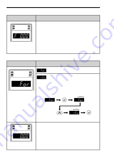
Table 6.1 Display Screens and Functions at Power-On

Display Screen

Function

Frequency Reference

Display

(default setting)

You can monitor and change the frequency reference
while the drive is running.

Note:

Set

o1-02 [Monitor Selection at Power-up]

to select

the data displayed when you first energize the drive.

Table 6.2 Drive Mode Display Screens and Functions

Display Screen

Function

Forward/Reverse Run

Selection

: The motor runs forward.

: The motor runs reverse.

Note:

Set

b1-04 [Reverse Operation Selection]

to prevent

the reverse Run command in applications, for
example fans or pumps, where reverse motor rotation
can be dangerous.

Figure 6.2 Setting Reverse Run

Output Frequency

Display

You can monitor the frequency output from the drive.

Summary of Contents for JVOP-KPLEA04A Series

Page 1: ...C Drive Option LED Keypad Installation Manual Type JVOP KPLEA04Axx JVOP KPLEA04Mxx To properly use the product read this manual thoroughly and retain for easy reference inspection and maintenance Ensu...

Page 2: ...This Page Intentionally Blank 2 YASKAWA TOEP C730600 74D LED Keypad Installation Manual...

Page 3: ...Information 6 2 Overview 7 3 Receiving 7 4 Component Names and Functions 9 LED Status Indicators 12 5 Installation Procedure 14 Section Safety 14 Remote Operation 14 Methods to Install a Remote Keypad...

Page 4: ...EMOTE Mode 48 Execute Auto Tuning 48 Read Parameter Settings from the Drive Backup 52 Write Parameters Saved in the Keypad to Another Drive Restore 54 Verify Parameters in Drive and Parameters Saved i...

Page 5: ...he manuals provide information about basic installation wiring operation procedures functions troubleshooting and maintenance The manuals also include important information about parameter settings an...

Page 6: ...not prevent it CAUTION Identifies a hazardous situation which if not avoided can cause minor or moderate injury NOTICE This signal word identifies a property damage message that is not related to per...

Page 7: ...d or modify drive parameter settings Back up restore and verify drive parameters Operate and stop the drive Monitor drive operation status Note This product has no clock function Compatible Products P...

Page 8: ...number on the option nameplate and the model shown in the purchase order are the same Immediately contact the distributor where you purchased the option or the Yaskawa sales office about problems wit...

Page 9: ...ames and Functions Figure 4 1 Keypad Components Key and LED Function A RUN LED Illuminates to show that the drive is operating the motor B REV LED Illuminates when a reverse Run command is active C AL...

Page 10: ...not switch between LOCAL Mode and REMOTE Mode when it is receiving a Run command from an external source Stop operation to enable the LO RE Selection Key when in Drive Mode Set o2 01 0 LO RE Key Func...

Page 11: ...oves the cursor to the right Clears drive faults ENTER Key Enters parameter values and settings Selects a menu item to navigate between displays K ESC Key Goes back to the previous display Push and ho...

Page 12: ...is in LOCAL Mode The drive received a Run command from an external source and the drive is not in Drive Ready READY condition The drive received a Fast Stop command The safety function shut off output...

Page 13: ...rive is in regular operation without alarms or faults DRV LED Illuminated The drive is in Drive Mode Flashing You are using DriveWorksEZ Note Refer to the DriveWorksEZ instruction manual for details r...

Page 14: ...ion cables more than the bend radius specifications If you bend the cables too much it can break the wires and loosen connections Note Use Yaskawa connection cables or recommended cables only Incorrec...

Page 15: ...he panel Phillips screwdriver 2 M3 M4 Installation support set A for mounting with screws model 900 192 933 001 Phillips screwdriver 2 M3 Wrench M4 Installation support set B for mounting with nut cla...

Page 16: ...t WV003 1 Installation support set A screw clamp 900 192 933 001 Encloses the keypad in the panel M3 screws 6 mm 0 24 in depth Phillips recessed pan head machine screws 2 M4 screws 10 mm 0 39 in depth...

Page 17: ...Dimensions mm in W H D D1 D2 R 1 W1 W2 H1 d 65 2 56 106 4 17 16 0 63 8 2 0 32 1 6 0 06 53 8 2 12 44 1 73 15 0 59 78 3 07 M3 1 Minimum bending radius NOTICE Damage to Equipment Do not bend the communi...

Page 18: ...t Installation 1 Use the dimensions in Table 5 2 and Figure 5 2 to cut an opening and tap two holes in the enclosure panel Figure 5 2 External Face Mount Enclosure Panel Cut Out Dimensions Table 5 2 E...

Page 19: ...n head screws to attach the keypad from the inside as shown in Figure 5 3 A Keypad B M3 screws C Enclosure panel D Screw mounting holes Figure 5 3 External Face Mount Installation 3 Push the tab on th...

Page 20: ...AWA TOEP C730600 74D LED Keypad Installation Manual 4 Remove the keypad connector and put the keypad connector in the holder on the front cover A Holder B Hook C Keypad connector Figure 5 5 Moving the...

Page 21: ...n Cable Internal Flush Mount Installation Installation support sets A or B sold separately are necessary for Internal Flush Mount installation The installation procedure is the same for installation s...

Page 22: ...OEP C730600 74D LED Keypad Installation Manual Figure 5 7 Internal Flush Mount Enclosure Panel Cut Out Dimensions Table 5 3 Enclosure Panel Cut Out Dimensions mm in W H W1 H1 d 64 0 5 2 52 0 02 130 5...

Page 23: ...Installation support set A C M3 screws D Screw mounting holes Figure 5 8 Mounting the Keypad to Installation Support Set A 3 Use the M4 screws included in the support set as shown in Figure 5 9 to at...

Page 24: ...Keypad Installation Manual A M4 screws B Enclosure panel Figure 5 9 Internal Flush Mount Installation 4 Push the tab on the top of the drive keypad and carefully pull forward to remove the keypad from...

Page 25: ...TOEP C730600 74D LED Keypad Installation Manual 25 5 Remove the keypad connector and put the keypad connector in the holder on the front cover A Holder B Hook C Keypad connector Figure 5 11 Moving th...

Page 26: ...0 74D LED Keypad Installation Manual 6 Use the extension cable to connect the drive to the keypad A Extension cable B Communications connector C Drive D Keypad E Cable connector Figure 5 12 Connecting...

Page 27: ...Installation 1 Use the dimensions in Table 5 4 and Figure 5 13 to cut an opening and tap two holes in the enclosure panel Figure 5 13 External Face Mount Enclosure Panel Cut Out Dimensions Table 5 4...

Page 28: ...ws to attach the keypad from the inside as shown in Figure 5 14 A Keypad B M3 screws C Enclosure panel D Screw mounting holes Figure 5 14 External Face Mount Installation 3 Use a slotted screwdriver t...

Page 29: ...ation Procedure YASKAWA TOEP C730600 74D LED Keypad Installation Manual 29 A Front cover lock Figure 5 15 Unlocking 4 Slide the front cover down and remove it from the drive Figure 5 16 Remove the Fro...

Page 30: ...edure 30 YASKAWA TOEP C730600 74D LED Keypad Installation Manual 5 Push on the tab on the right side of the keypad then pull the keypad forward to remove it from the drive Figure 5 17 Removing the Inc...

Page 31: ...n Cable Internal Flush Mount Installation Installation support sets A or B sold separately are necessary for Internal Flush Mount installation The installation procedure is the same for installation s...

Page 32: ...EP C730600 74D LED Keypad Installation Manual Figure 5 19 Internal Flush Mount Enclosure Panel Cut Out Dimensions Table 5 5 Enclosure Panel Cut Out Dimensions mm in W H W1 H1 d 64 0 5 2 52 0 02 130 5...

Page 33: ...Installation support set A C M3 screws D Screw mounting holes Figure 5 20 Mounting the Keypad to Installation Support Set A 3 Use the M4 screws included in the support set as shown in Figure 5 21 to a...

Page 34: ...allation Manual A M4 Screws B Enclosure panel Figure 5 21 Internal Flush Mount Installation 4 Use a slotted screwdriver to unlock the front cover of the drive Use a slotted screwdriver with a tip widt...

Page 35: ...ation Procedure YASKAWA TOEP C730600 74D LED Keypad Installation Manual 35 A Front cover lock Figure 5 22 Unlocking 5 Slide the front cover down and remove it from the drive Figure 5 23 Remove the Fro...

Page 36: ...edure 36 YASKAWA TOEP C730600 74D LED Keypad Installation Manual 6 Push on the tab on the right side of the keypad then pull the keypad forward to remove it from the drive Figure 5 24 Removing the Inc...

Page 37: ...4D LED Keypad Installation Manual 37 7 Use the extension cable to connect the drive to the keypad A Extension cable B Communications connector C Drive D Keypad E Cable connector Figure 5 25 Connecting...

Page 38: ...ASKAWA TOEP C730600 74D LED Keypad Installation Manual 6 Basic Operation Keypad Display Function Hierarchy Figure 6 1 Keypad Display Function Hierarchy XX XX XX X XX XX XX XX XX XX XX XX XX XX XX XX X...

Page 39: ...ode will illuminate in LOCAL Mode If you push in Programming Mode it will not rotate the motor The actual setting value will replace XX in the diagram Set b1 08 Run Command Select in PRG Mode to accep...

Page 40: ...ion at Power up to select the data displayed when you first energize the drive Table 6 2 Drive Mode Display Screens and Functions Display Screen Function Forward Reverse Run Selection The motor runs f...

Page 41: ...ay Monitors drive output current Output Voltage Display default setting Monitors the output voltage reference Set o1 01 User Monitor Selection to change the item shown on this screen Monitor Display S...

Page 42: ...ameters shown in the Setup Mode are different for different A1 06 Application Preset settings Parameter Setting Mode Shows and sets all parameters Auto Tuning Mode The drive automatically calculates a...

Page 43: ...erence Selection 1 Keypad Push and on the keypad to operate the drive Example drive operation Change the frequency reference from F0 00 0 Hz to F6 00 6 Hz 1 Push and hold to show the frequency referen...

Page 44: ...equency reference display screen 7 Push to rotate the motor at 6 Hz and illuminate 8 Push flashes while the motor decelerates turns OFF when the motor comes to a complete stop Monitoring Drive Status...

Page 45: ...ows the monitor details Change Parameter Setting Values The following example drive operation shows how to change C1 01 Acceleration Time 1 from 10 0 s default setting to 20 0 s 1 Push and hold to sho...

Page 46: ...complete the parameter change The LED display shows and the display automatically goes back to the Parameter Settings screen Verifying and Changing Parameter Settings Verify Menu The Verify Menu shows...

Page 47: ...o scroll through the changed parameters 4 To change a parameter again in the Verify Menu push or to select the parameter to change then push 5 Push to select the digit to change The digit will flash P...

Page 48: ...ause serious injury or death 1 Make sure that is OFF and the drive is stopped Note Switching between LOCAL Mode and REMOTE Mode is not possible when the drive receives a Run command 2 Push and hold to...

Page 49: ...tart suddenly during Auto Tuning and cause serious injury or death WARNING Electrical Shock Hazard During Auto Tuning the motor will receive high voltage when the motor is stopped Do not touch the mot...

Page 50: ...e cannot be identified despite the existence of an Endx error Er xx indicates that Auto Tuning has not completed successfully Fix the cause of the detected error and perform Auto Tuning again Release...

Page 51: ...ay automatically goes back to the Parameter Settings screen 7 Push to select Motor Rated Power and push 8 Push to select the digit to change The digit will flash Push to change the value Input informa...

Page 52: ...A1 02 3 Control Method Selection Closed Loop Vector 11 Push 12 Push illuminates and Auto Tuning starts For Rotational Auto Tuning the drive injects current into the motor for about 1 minute before ro...

Page 53: ...ackup approximately 100 000 times 1 Make sure that is OFF and the drive is stopped 2 Push and hold to show the frequency reference display screen 3 Push or to show Parameter Settings Mode 4 Push 5 Pus...

Page 54: ...ading The display automatically goes back to the Parameter Settings screen Write Parameters Saved in the Keypad to Another Drive Restore This operation example writes all parameter settings saved in t...

Page 55: ...h 7 Push and select Restore and push to write parameters to the drive The LED display shows while writing The keypad shows when writing ends The display automatically goes back to the Parameter Settin...

Page 56: ...nd the drive is stopped 2 Push and hold to show the frequency reference display screen 3 Push or to show Parameter Settings Mode 4 Push 5 Push to show and push to move the flashing digit 6 Push Up arr...

Page 57: ...gs screen when the parameter settings match The keypad shows or other errors if the parameter settings did not match 8 After you verify the parameter settings push and hold to go back to the frequency...

Page 58: ...Option PCB 1 0 3 b1 15 01C4 Frequency Reference Selection 2 Sets the input method for frequency reference 2 0 Keypad 1 Analog Input 2 Memobus Modbus Communications 3 Option PCB 4 Pulse Train Input 0...

Page 59: ...the Run command source for the drive is REMOTE external and not assigned to the keypad 0 Disabled 1 Enabled 1 0 1 o2 05 0509 Home Mode Freq Ref Entry Mode Sets the function that makes it necessary to...

Page 60: ...when o3 01 1 Copy Keypad Function Selection Backup drive keypad 0 Disabled 1 Enabled 0 0 1 8 Fault Diagnostics and Measures Fault Displays The drive keypad shows Fault Error codes to indicate specific...

Page 61: ...move the keypad and connect it again Faulty keypad Replace the keypad Drive control circuit error Re energize the drive Replace the drive oPr Keypad Connection Fault The keypad is not securely connect...

Page 62: ...ycle the battery Discard used batteries as specified by the battery manufacturer Customers are responsible for microSD card data protection PC functions that format and delete the data may not be suff...

Page 63: ...ng Ambient Humidity 95 RH or less no condensation Storage Ambient Temperature 20 C to 70 C 4 F to 158 F short term storage temperature during transport Area of Use Indoor the area without corrosive ga...

Page 64: ...nty Scope Failure diagnosis In principle Yaskawa requests that the primary fault diagnosis be conducted by your company However Yaskawa or our service network can conduct a fault diagnosis on behalf o...

Page 65: ...o your company or damage to non Yaskawa products such as to you or your customers due to the failure of our products or compensation for other business whether within or outside of the warranty period...

Page 66: ...ire documentation Chapter 1 Addition Compatible Models GA500 Chapter 2 Chapter 5 Chapter 9 Addition Disposal Instructions March 2019 2 All Revision Reviewed and corrected entire documentation Chapter...

Page 67: ...YASKAWA TOEP C730600 74D LED Keypad Installation Manual 67...

Page 68: ...regulations as stipulated in the Foreign Exchange and Foreign Trade Regulations Therefore be sure to follow all procedures and submit all relevant documentation according to any and all rules regulati...

Reviews: