


14
YASKAWA
TM.iQp.02 iQpump Drive Programming Manual
■
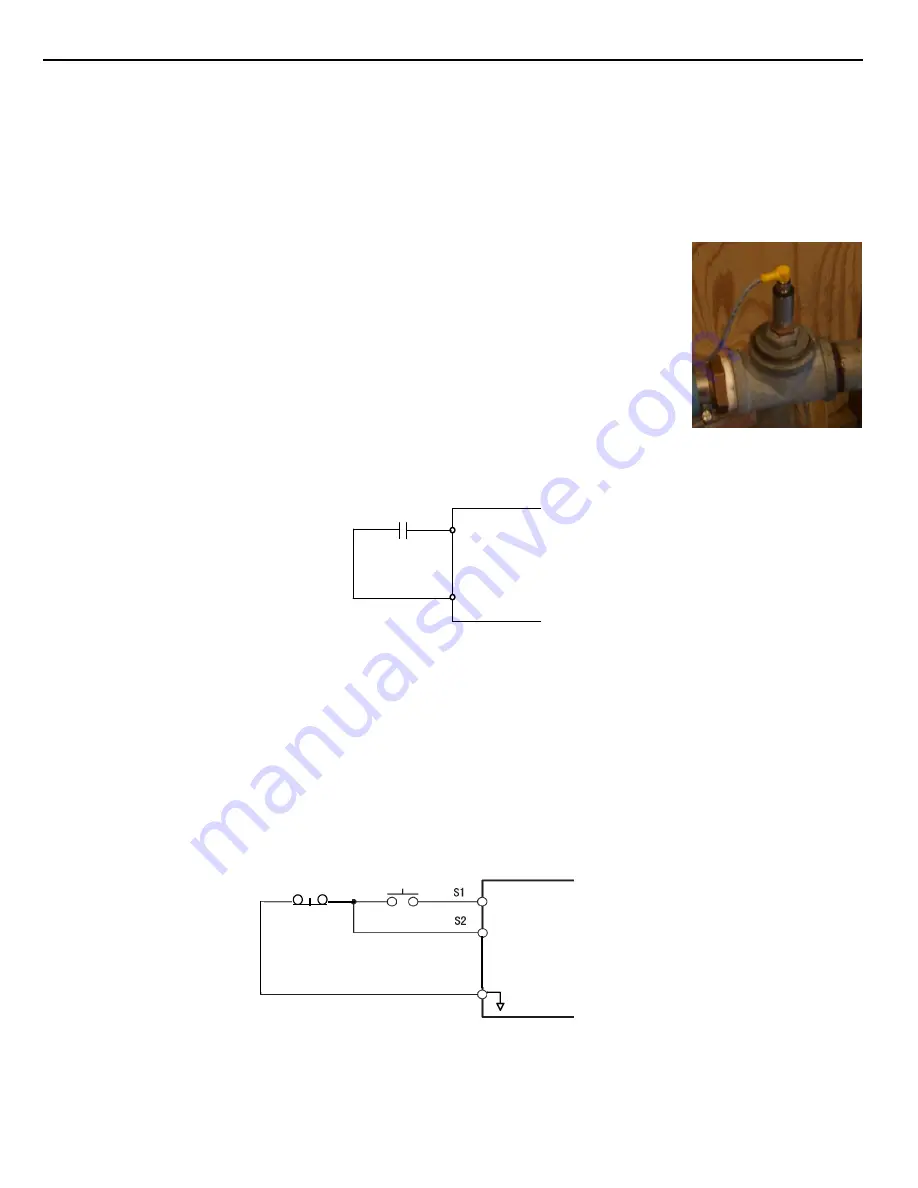
Feedback Device
The iQpump Controller requires a feedback device (e.g. Pressure transducer, flow meter, etc.) to perform automatic system regulation.
Any analog 0~10 V or 4-20 mA feedback device can be used in combination with the iQpump controller.
Connecting Your Feedback Device to the iQpump Controller
Note:
The factory default setting for the iQpump controller is 4~20 mA feedback device connected to
analog input A2.
To successfully operate the iQpump drive remotely, an external run command must be received by the
Drive. Parameter b1-02 specifies from where the run command will be accepted.
Although the Run Source and the Reference Source (b1-01) are normally taken from the same source (e.g.
digital operator, terminals or serial communication), this is not always the case.
To issue a run command from the digital operator:
Set b1-02 = “0: Operator,” and use the HAND and
OFF buttons to start and stop the Drive.
To issue the run command from the terminals:
Set b1-02 = “1: Terminals,” and select between 2-wire
and 3-wire control operation by doing the following:
2-Wire Control
The factory default setting is for 2-wire operation. In the 2-wire configuration a closure between S1 and SN will be
interpreted as a Forward Run command by the Drive.
Figure 1.7
Figure 7 2-Wire Control
3-Wire Control
When any of the multi-function digital input parameters, H1-01 through H1-05, is set to 0, terminals S1 and S2 become
Run and Stop, respectively. The multi-function digital input that was set to 0 will function as a Forward/Reverse input for the iQpump
Drive. When the Forward/Reverse input is open the iQpump drive will run in the Forward direction and when the input is closed, the
iQpump drive will run in the Reverse direction.
In 3-wire operation a momentary closure (> 50mS) of S1 will cause the iQpump drive to run provided that S2 is held closed. The iQpump
drive will stop anytime the S2-SN connection is broken. If the 3-wire configuration is implemented via a 3-wire Initialization (A1-03 =
“3330: 3-Wire Initial”), then terminal S3 becomes the Forward/Reverse input.
Note:
Reverse operation is disabled in the iQpump drive; however, in 3-wire control, one of the multi-function digital inputs
needs to be programmed to 0. Otherwise, the 3-wire control will not work.
Figure 1.8
Figure 8 3-Wire Control
To issue a run command via serial communication:
Set b1-02 = “2: Serial Com” and connect the RS-485/422 serial communication
cable to R+, R-, S+, and S- on the removable terminal block.
• Modbus Plus Option Card CM071
Manual: IG.AFD.17
• Modbus TCP/IP Option Card CM090
Manual: IG.AFD.25
• EtherNet/IP Option Card CM092
Manual: IG.AFD.26
S1
S2
SN
FWD Run/Stop
REV Run/Stop
3-wire control
Stop switch
(NC contact)
Operation switch
(NO contact)
Run command
(run on momentary close)
Stop command
(stop on momentary open)
Sequence input common
SN
Summary of Contents for iQpump Series
Page 1: ...iQpump Drive Programming Manual Document Number TM iQp 02...
Page 204: ...204 YASKAWA TM iQp 02 iQpump Drive Programming Manual THIS PAGE INTENTIONALLY LEFT BLANK...
Page 208: ...208 YASKAWA TM iQp 02 iQpump Drive Programming Manual THIS PAGE INTENTIONALLY LEFT BLANK...
Page 209: ...YASKAWA TM iQp 02 iQpump Drive Programming Manual 209 THIS PAGE INTENTIONALLY LEFT BLANK...


