background image

4 Receiving

YASKAWA

TOEPC7106170VA GA800 600 V Drive Installation & Primary Operation

9

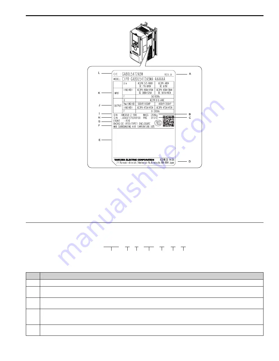
A - Product Revision
B - Weight
C - Drive software version
D - The address of the head office of Yaskawa

Electric Corporation

E - Standards compliance
F - Surrounding air temperature

G - Enclosure protection design
H - Serial number
I - Lot number
J - Output specifications
K - Input specifications
L - Catalog code

Figure 4.1 Nameplate Example

How to Read the Catalog Code

Use the information in

Figure 4.2

and

Table 4.1

to read the drive catalog codes.

Figure 4.2 Drive Catalog Code

Table 4.1 Catalog Code Details

No.

Description

1

GA800 Series

2

Region code

U: Americas

3

Input power supply voltage

5: Three-Phase AC 600 V

4

Rated output current

Note:

Refer to the rated output current list for more information.

5

EMC noise filter

A: No built-in EMC filter

GA80   U   5   382   A    B   M

1

2

3

4

5

6

7

Summary of Contents for GA800 600 V Drive

Page 1: ...GA800 600 V Drive AC Drive for Industrial Applications Installation Primary Operation Catalog Code GA80U5xxxxxxx 600 V class 400 to 500 HP ND PDF ...

Page 2: ...This Page Intentionally Blank 2 YASKAWA TOEPC7106170VA GA800 600 V Drive Installation Primary Operation ...

Page 3: ...ounting Dimensions IP20 13 Moving the Drive 14 Using the Hanging Brackets to Move the Drive 14 Installation Position and Distance 14 Removing Reattaching Covers 15 Removing Reattaching the Cover Using Procedure B 15 7 Electrical Installation 18 Standard Connection Diagram 18 Main Circuit Terminal Functions 22 Motor and Main Circuit Connections 22 Main Circuit Terminal Block Wiring 23 Wire Selectio...

Page 4: ...utput Signals for MFAO Terminals FM AM 46 Switch ON Termination Resistor for MEMOBUS Modbus Communications 47 11 Drive Control Duty Modes and Programming 47 Selecting the Control Method 47 Drive Duty Modes 48 Auto Tuning 48 Drive Parameters 49 12 UL Standards 53 Area of Use 53 Main Circuit Wire Gauges and Tightening Torques 53 Closed Loop Crimp Terminals 54 Factory Recommended Branch Circuit Prote...

Page 5: ...Drive Output Safe Torque Off 63 Safe Disable Monitor Output Function and Keypad Display 64 Validating the Safe Disable Function 64 16 Disposal Instructions 65 WEEE Directive 65 17 Maintenance 65 18 Troubleshooting 66 Fault 66 Minor Faults Alarms 74 Parameter Setting Errors 78 Auto Tuning Errors 80 Backup Function Operating Mode Display and Errors 82 Revision History 84 ...

Page 6: ...nly for the quality of our products in compliance with standards and specifications that are described in the manual Yaskawa does not offer other warranties either explicit or implied Injuries property damage and lost business opportunities caused by improper storage or handling and negligence oversight on the part of your company or your customers will void Yaskawa s warranty for the product Note...

Page 7: ...arthing conductor When a residual current operated protective or monitoring device prevents direct or indirect contact always use a type B Ground Fault Circuit Interrupter GFCI as specified by IEC EN 60755 If you do not use the correct GFCI it can cause serious injury or death WARNING Electrical Shock Hazard Ground the neutral point on the power supply of drive models 5xxxB C to comply with the EM...

Page 8: ...skawa sales representative if you are considering the application of this product for special purposes such as machines or systems used for passenger cars medicine airplanes and aerospace nuclear power electric power or undersea relaying WARNING Injury to Personnel When you use this product in applications where its failure could cause the loss of human life a serious accident or physical injury y...

Page 9: ...t specifications K Input specifications L Catalog code Figure 4 1 Nameplate Example How to Read the Catalog Code Use the information in Figure 4 2 and Table 4 1 to read the drive catalog codes Figure 4 2 Drive Catalog Code Table 4 1 Catalog Code Details No Description 1 GA800 Series 2 Region code U Americas 3 Input power supply voltage 5 Three Phase AC 600 V 4 Rated output current Note Refer to th...

Page 10: ...e To get the OLV CLV and AOLV specifications do Rotational Auto Tuning To get the longest product life install the drive in an environment that meets the necessary specifications Table 5 1 Control Characteristics Item Specification Control Methods V f Control V f V f Control with Encoder CL V f Open Loop Vector OLV Closed Loop Vector CLV Advanced Open Loop Vector AOLV Carrier Frequency Models 5382...

Page 11: ... V f Characteristics Select from 15 pre defined V f patterns or a user set V f pattern Main Control Functions Torque Control Droop Control Speed Torque Control Switching Feed Forward Control Zero Servo Function Restart After Momentary Power Loss Speed Search Overtorque Undertorque Detection Torque Limit 17 Step Speed max Accel Decel Switch S curve Acceleration Deceleration 3 wire Sequence Auto Tun...

Page 12: ... 10 Three phase AC power supply 500 V to 600 Vat 50 60 Hz DC power supply 675 V to 848 V Ambient Temperature Setting IP20 UL Open Type Heatsink External Mounting 10 C to 50 C 14 F to 122 F IP55 UL Type 12 Heatsink External Mounting front side 10 C to 50 C 14 F to 122 F IP55 UL Type 12 Heatsink External Mounting back side 10 C to 40 C 14 F to 104 F When installing the drive in an enclosure use a co...

Page 13: ...12 Heatsink External Mounting front side 10 C to 50 C 14 F to 122 F IP55 UL Type 12 Heatsink External Mounting back side 10 C to 40 C 14 F to 104 F 6 Mechanical Installation This section gives information about the standard environment for correct installation Drive Exterior and Mounting Dimensions IP20 For additional IP20 drive dimension information refer to the Technical Reference manual documen...

Page 14: ...it is suspended Before you install the drive make sure that you read these precautions WARNING Crush Hazard Before you hang the drive vertically use screws to correctly attach the drive front cover and other drive components If you do not secure the front cover it can fall and cause minor injury WARNING Crush Hazard When you use a crane or hoist to lift the drive during installation or removal pre...

Page 15: ...ce 5382 5472 Procedure B 15 Removing Reattaching the Cover Using Procedure B DANGER Electrical Shock Hazard Do not examine connect or disconnect wiring on an energized drive Before servicing disconnect all power to the equipment and wait for the time specified on the warning label at a minimum The internal capacitor stays charged after the drive is de energized The charge indicator LED extinguishe...

Page 16: ...er forward to remove it from the drive A Pull forward to remove the front cover B Unhook the tabs found on the sides of the front cover Figure 6 5 Pull Forward to Remove the Front Cover 4 Remove the front cover from the drive Figure 6 6 Remove the Front Cover Reattach the Front Cover Wire the drive and other peripheral devices then reattach the front cover Note Wire the grounding terminals first m...

Page 17: ...s of the front cover Note Make sure that you do not pinch wires or signal lines between the front cover and the drive before you reattach the cover Figure 6 8 Reattach the Front Cover 3 Reattach the keypad to the original position Remove the Terminal Cover 1 Loosen the screws on the terminal cover then pull down on the cover CAUTION Crush Hazard Loosen the cover screws Do not fully remove them If ...

Page 18: ...s to make sure that the drive is safe If you do work on the drive when it is energized it will cause serious injury or death from electrical shock WARNING Electrical Shock Hazard De energize the drive and wait 5 minutes minimum until the Charge LED turns off Remove the front cover and terminal cover to do work on wiring circuit boards and other parts Use terminals for their correct function only I...

Page 19: ... it changes the I O terminal functions for the drive and it can cause equipment to operate unusually This can cause serious injury or death NOTICE Fire Hazard Install sufficient branch circuit short circuit protection as specified by applicable codes and this manual The drive is suited for circuits that supply not more than 100 000 RMS symmetrical amperes 600 Vac maximum 600 V Class Incorrect bran...

Page 20: ...in input MFAI 3 PTC input 0 V Control Circuit B1 1 2 B2 2 kΩ 0 10 V 4 mA to 20 mA 0 10 V FM AM 0 V 0 V AC FM AM AC E G S1 S2 MA M1 M2 MB MC V r1 s1 t1 D M4 M3 M5 M6 OFF ON I I I V V V AI PTC CN5 C CN5 B CN5 A V I FM AM 1 2 SA 1 M TB1 TB2 A A B Z B Z FE SD AO IG BO IG ZO IG IP IG U X 2 3 3 4 5 6 8 8 9 7 8 10 12 12 13 14 14 14 15 13 16 20 22 22 11 17 18 19 18 19 21 ...

Page 21: ...supply sinking sourcing mode or internal external power supply NOTICE Damage to Equipment Do not close the circuit between terminals SP SN If you close the circuits terminals SC SP and terminals SC SN it will cause damage to the drive Sinking Mode Install a jumper between terminals SC and SP NOTICE Damage to Equipment Do not close the circuit between terminals SC SN If you close the circuits termi...

Page 22: ...onnect a commercial power supply S L2 T L3 U T1 Drive output To connect a motor V T2 W T3 1 DC power supply input 1 and Braking unit connection 3 and To connect peripheral devices for example DC power input Braking unit 3 Protective Earth To ground the drive Motor and Main Circuit Connections WARNING Electrical Shock Hazard Do not connect terminals R L1 S L2 T L3 U T1 V T2 W T3 1 2 3 B1 or B2 to t...

Page 23: ...e protective ground wire disconnects You can also connect a protective ground wire that has a minimum cross sectional area of 10 mm2 copper wire or 16 mm2 aluminum wire If you do not obey the standards and regulations it can cause serious injury or death The leakage current of the drive will be more than 3 5 mA in models 5382 to 5472 Think about line voltage drop before selecting wire gauges Selec...

Page 24: ... Hex self locking nut 35 310 1 4 0 4P 3 0 400 300 400 M12 Hex self locking nut 35 310 3 1 0 4P 2 4 0 4 0 M12 Hex self locking nut 35 310 1 1 300 M12 Hex bolt slotted 32 40 283 354 5472 R L1 S L2 T L3 3 0 4P 2 0 300 250 300 M12 Hex self locking nut 35 310 U T1 V T2 W T3 3 0 4P 2 0 300 250 300 M12 Hex self locking nut 35 310 1 4 0 4P 3 0 400 300 400 M12 Hex self locking nut 35 310 3 1 0 4P 2 4 0 4 0...

Page 25: ...torque as specified by Yaskawa Use tools that fit the shape of the screw head to tighten and loosen the terminal block screws Make sure that there are no loose stranded wires or frayed wires after wiring is complete Main Circuit Terminal Block Wiring Procedure Remove the terminal cover before wiring the main circuit terminal block 1 Remove the screws on the terminal block cover and pull the termin...

Page 26: ...lip this area Figure 7 7 Clip the Cutaway Section of the Wiring Cover Note Different drive models have different wiring covers Remove only the areas from the wiring cover that apply to the wired terminal If you remove areas that do not apply to the wired terminal the drive will not keep its IP20 protective level Make sure that you hold the cutaway section tightly when you remove pieces of the cuta...

Page 27: ...rimary Operation 27 6 Attach the wiring cover and terminal block cover to their initial positions and tighten the screws on the terminal block cover Figure 7 8 Reattach the Wiring Cover 7 Put the terminal cover back in its initial position 8 Keypad Names and Functions Figure 8 1 Keypad ...

Page 28: ...top commands and the frequency reference command REMOTE Operated from the control circuit terminal or serial transmission Use the frequency reference source entered in b1 01 and the Run command source selected in b1 02 F LO RE Selection Key Switches drive control for the Run command and frequency reference between the keypad LOCAL and an external source REMOTE Note Stop operation to enable the LO ...

Page 29: ... 4 F to 185 F M Insulation Sheet An insulating sheet is attached to the keypad battery to prevent battery drain Remove the insulation sheet before you use the keypad for the first time N Nameplate Shows the model lot number and FLASH number of the keypad Note Make sure that you use a keypad with FLASH number 1004 or later Keypads with FLASH numbers 1003 and earlier will not show characters correct...

Page 30: ...8 Keypad Names and Functions 30 YASKAWA TOEPC7106170VA GA800 600 V Drive Installation Primary Operation Keypad Mode and Menu Displays Figure 8 2 Keypad Functions and Display Levels ...

Page 31: ...ommand from an external source while in Programming Mode Set b1 08 0 Disregard RUN while Programming to reject the Run command from an external source while in Programming Mode default Set b1 08 1 Accept RUN while Programming to accept the Run command from an external source while in Programming Mode Set b1 08 2 Allow Programming Only at Stop to prevent changes from Drive Mode to Programming Mode ...

Page 32: ... For example in Programming Mode or when is flashing C RUN Illuminated The drive is in regular operation Flashing 1 The drive is decelerating to stop The drive received a Run command with a frequency reference of 0 Hz but the drive is not set for zero speed control The drive received a DC Injection Braking command Flashing Quickly 1 The drive received a Run command from the MFDI terminals and is s...

Page 33: ... and deceleration times 5 Run the motor without a load 6 Make sure that the drive is operating correctly and make sure that the host controller is sending commands to the drive 7 Connect the load 8 Run the motor 9 Make sure that the drive is operating correctly 10 Fine tune and set application parameters such as PID 11 Do a final operation check and make sure that parameter settings are correct Th...

Page 34: ...e dioxide lithium battery or an equivalent battery with these properties Nominal voltage 3 V Operating temperature range 20 C to 85 C 4 F to 185 F Nominal battery life 2 years 20 C 68 F ambient temperature 3 Select Setup Wizard and follow the instructions shown on the keypad until the setup wizard completes The drive and motor are prepared for operation Note Refer to Disable the Initial Setup Scre...

Page 35: ...l Time then push 6 Push or to select C1 01 then push 7 Push or to select the specified digit then push or to select the correct number Push Default to set the parameter to factory default Push Min Max to show the minimum value or the maximum value on the display 8 Push to keep the changes 9 Continue to change parameters then push Back Home to go back to the home screen after you change all the app...

Page 36: ...en the drive is energized Control Circuit Terminal Block Functions Hx xx parameters set functions for the multi function input and output terminals WARNING Sudden Movement Hazard Correctly wire and test all control circuits to make sure that the control circuits operate correctly If you use a drive that has incorrect control circuit wiring or operation it can cause death or serious injury WARNING ...

Page 37: ...C MFDI selection common SP MFDI power supply 24 Vdc Safe Disable Input H1 Safe Disable input 1 Remove the jumper between terminals H1 HC and H2 HC to use the Safe Disable input 24 V 6 mA ON Normal operation OFF Coasting motor Internal impedance 4 7 kΩ OFF Minimum OFF time of 2 ms H2 Safe Disable input 2 HC Safe Disable function common Safe Disable function common NOTICE Do not close the circuit be...

Page 38: ...t 0 V to 10 V 0 to 100 10 V to 10 V 100 to 100 4 mA to 20 mA receiver recommended impedance 250 Ω Note Select with jumper switch S5 and H4 07 Terminal FM Signal Level Select or H4 08 Terminal AM Signal Level Select AM Analog monitor output 2 Output current AC Monitor common 0 V External Power Supply Input Terminals Refer to Table 10 4 for a list of the functions of the external power supply input ...

Page 39: ...g torque for the terminal screws is shown on the reverse side or the lower front side of the front cover Figure 10 2 Tightening Torque Display Location Reverse side of Front Cover Figure 10 3 Tightening Torque Display Location Lower Front Side of Front Cover Control Circuit Wire Gauges and Tightening Torques Use the tables in this section to select the correct wires Use shielded wire to wire the c...

Page 40: ...oards while the drive is energized If you touch the internal components of an energized drive it can cause serious injury or death NOTICE Do not let wire shields touch other signal lines or equipment Insulate the wire shields with electrical tape or shrink tubing If you do not insulate the wire shields it can cause a short circuit and damage the drive Note Isolate control circuit wiring from main ...

Page 41: ...you cause damage to the LED status ring board the LEDs will not function correctly Note You can temporarily store the LED status ring board with the temporary placement holes on the drive The location of the temporary placement holes is different on different drive models A Drive front B LED status ring board C Temporary placement holes Figure 10 5 Remove the LED Status Ring Board A Drive front B ...

Page 42: ... wires lightly twisted C Pull back the shielding and lightly twist the end with your fingers to keep the ends from fraying D Remove approximately 5 5 mm 0 21 in of the covering at the end of the wire when you do not use crimp ferrules E Blade width of 2 5 mm 0 1 in or less F Blade thickness of 0 4 mm 0 01 in or less Figure 10 8 Wiring Procedure for the Control Circuit Note Do not solder the core w...

Page 43: ...Function Default A DIP switch S2 Enables and disables the MEMOBUS Modbus communications termination resistor OFF B Jumper switch S5 FM AM Sets terminals FM and AM to voltage or current output FM V voltage output AM V voltage output C DIP switch S1 1 A1 Sets the input signal type voltage current V voltage input DIP Switch S1 2 A2 Sets the input signal type voltage current I current input DIP switch...

Page 44: ...ower supply changes the voltage level of the pulse train output signal Keep the voltage from an external source between 10 8 Vdc to 16 5 Vdc Adjust the load impedance to keep the current at 16 mA or lower External Power Supply V Load Impedance kΩ Sinking current mA 10 8 Vdc to 16 5 Vdc 1 0 kΩ or more 16 mA maximum A External power supply B Load Impedance C Sinking current Figure 10 13 Wiring to Us...

Page 45: ...evel A1 Voltage input S1 1 V Default H3 01 0 0 V to 10 V 0 to 100 input impedance 20 kΩ 1 10 V to 10 V 100 to 100 input impedance 20 kΩ Current input I 2 4 mA to 20 mA 0 to 100 input impedance 250 Ω 3 0 mA to 20 mA 0 to 100 input impedance 250 Ω A2 Voltage input S1 2 V H3 09 0 0 V to 10 V 0 to 100 input impedance 20 kΩ 1 10 V to 10 V 100 to 100 input impedance 20 kΩ Current input I Default 2 4 mA ...

Page 46: ...AI Set MFAI Terminal A3 to PTC Input Set terminal A3 as an MFAI or as the PTC input for motor overload protection Use DIP switch S4 to set the input function Figure 10 15 Location of DIP Switch S4 Terminal Settings for DIP Switches Description A3 AI Default Functions as an MFAI terminal Set H3 06 Terminal A3 Function Selection to select the input function PTC Functions as the PTC input terminal Se...

Page 47: ...485 interface Figure 10 17 Location of DIP Switch S2 Table 10 10 MEMOBUS Modbus Communications Termination Resistor Setting DIP Switch S2 Description ON The built in termination resistor is ON OFF Default The built in termination resistor is OFF 11 Drive Control Duty Modes and Programming Selecting the Control Method This section gives information about these basic control methods V f Control V f ...

Page 48: ...ere are no issues related to safety in the area around the drive and motor Increased motor frequency can cause serious injury or death WARNING Sudden Movement Hazard Before you do Rotational Auto Tuning disconnect the load from the motor The load can move suddenly and cause serious injury or death Auto Tuning automatically sets parameters on the drive connected to the motor You must input some par...

Page 49: ...0100 RUN Language Selection Sets the language for the LCD keypad 0 English 1 Japanese 2 German 3 French 4 Italian 5 Spanish 6 Portuguese 7 Chinese 8 Czech 9 Russian 10 Turkish 11 Polish 12 Greek A1 02 0102 Control Method Selection Sets the control method for the drive application and the motor 0 V f Control 1 V f Control with Encoder 2 Open Loop Vector 3 Closed Loop Vector 4 Advanced Open Loop Vec...

Page 50: ...ncy for the transistors in the drive 1 2 0 kHz 2 5 0 kHz 3 8 0 kHz 4 10 0 kHz 5 12 5 kHz 6 15 0 kHz 7 Swing PWM1 Audible Sound 1 8 Swing PWM2 Audible Sound 2 9 Swing PWM3 Audible Sound 3 A Swing PWM4 Audible Sound 4 F User Defined C6 03 to C6 05 d1 01 to d1 16 0280 0291 RUN Reference 1 to 16 Sets the frequency reference in the units from o1 03 Frequency Display Unit Selection d1 17 0292 RUN Jog Re...

Page 51: ...ut to MFAI terminal A1 H3 04 0412 RUN Terminal A1 Bias Setting Sets the bias of the analog signal input to MFAI terminal A1 H3 05 0413 Terminal A3 Signal Level Select Sets the input signal level for MFAI terminal A3 0 0 to 10V Lower Limit at 0 1 10 to 10V Bipolar Reference 2 4 to 20 mA 3 0 to 20 mA H3 06 0414 Terminal A3 Function Selection Sets the function for MFAI terminal A3 H3 07 0415 RUN Term...

Page 52: ...utput from the MFAO terminal AM H4 05 0421 RUN Terminal AM Analog Output Gain Sets the gain of the monitor signal that is sent from MFAO terminal AM H4 06 0422 RUN Terminal AM Analog Output Bias Sets the bias of the monitor signal that is sent from MFAO terminal AM H4 07 0423 Terminal FM Signal Level Select Sets the MFAO terminal FM output signal level 0 0 to 10 Vdc 1 10 to 10 Vdc 2 4 to 20 mA H4 ...

Page 53: ...ed in accordance with UL standard UL 508C and has been verified to be in compliance with UL standards Machines and devices integrated with this product must satisfy the following conditions for compliance with UL standards Area of Use Install this product in a location with Overvoltage Category III and pollution degree 2 or less as specified in UL 508C Ambient Temperature Setting Maintain the ambi...

Page 54: ...p crimp terminals and heat shrinkable tubing from PANDUIT Corp Comply with local standards for correct wire gauges in the region where the drive is used Use the tools recommended by PANDUIT Corp to crimp the closed loop terminals Refer to Table 12 1 to select crimp terminals as specified by drive model and wire gauge Note To comply with UL standards use only insulated crimp terminals or crimp term...

Page 55: ...des Yaskawa recommends the NEC class 1 circuit conductor Use the UL approved class 2 power supply for external power supply Table 12 3 Control Circuit Terminal Power Supplies Input Output Terminals Power Supply Specifications Digital input S1 to S8 SN SC SP Uses the LVLC power supply in the drive Use the UL Listed class 2 power supply for external power supply Analog input A1 to A3 AC V V Uses the...

Page 56: ...c thermal protector that aligns with the permitted load characteristics of the motor to select motor protection The electronic thermal protector of the drive uses these items to calculate motor overload tolerance and supply overload protection for the motor Output Current Output Frequency Motor thermal characteristics Time characteristics If the drive detects motor overload the drive will trigger ...

Page 57: ...otor operates at frequencies less than 60 Hz the drive will detect oL1 The drive triggers a fault relay output and the motor coasts to stop 2 Constant Torque 10 1 Speed Range Use this setting for drive dedicated motors with a speed range for constant torque of 1 10 The speed control for this motor is 10 to 100 when at 100 load Operating slower than 10 speed at 100 load will cause motor overload Lo...

Page 58: ...frequency to maximize the motor cooling ability If the motor operates at frequencies less than commercial line power the drive will detect oL1 The drive triggers a fault relay output and the motor coasts to stop L1 02 Motor Overload Protection Time No Hex Name Description Default Range L1 02 0481 Motor Overload Protection Time Sets the operation time for the electronic thermal protector of the dri...

Page 59: ... turns OFF 2 Fast Stop Use C1 09 The drive stops the motor in the deceleration time set in C1 09 Fast Stop Time Fault relay output terminal MA MC turns ON and MB MC turns OFF 3 Alarm Only The keypad shows oH3 and operation continues The output terminal set for Alarm H2 01 to H2 03 10 turns ON L1 04 Motor Thermistor oH Fault Select No Hex Name Description Default Range L1 04 0483 Motor Thermistor o...

Page 60: ...friendly use period for this product is 15 years This period is not the product warranty period Information on Hazardous Substances in This Product Table 13 1 shows the details on hazardous substances contained in this product Table 13 1 Contents of Hazardous Substances in This Product Parts Name Hazardous Substances Lead Pb Mercury Hg Cadmium Cd Hexavalent Chromium Cr VI Polybrominated Biphenyls ...

Page 61: ...ption Input Output Input 2 Safe Disable input H1 H2 Signal ON level 18 Vdc to 28 Vdc Signal OFF level 4 Vdc to 4 Vdc Output 1 MFDO safety monitor output for external device monitor EDM Response time from when the input opens to when the drive output stops 3 ms or less Response time from when the H1 and H2 terminal inputs open to when the EDM signal operates 20 ms or less Failure probability Less f...

Page 62: ...G Sudden Movement Hazard When you clear the Safe Disable input make sure that the Safe Disable Monitor output operates correctly as the specification for Safe Disable function If the Safe Disable circuit does not operate correctly it can cause serious injury or death WARNING Sudden Movement Hazard Regularly examine the Safe Disable input and all other safety features A system that does not operate...

Page 63: ... and the motor always coasts to stop The b1 03 Stopping Method Selection setting does not have an effect on the stopping method The Safe Torque Off status is only possible with the Safe Disable function Clear the Run command to stop the drive Turning off drive output a baseblock condition Safe Torque Off Note When it is necessary to ramp to stop the motor do not turn off terminals H1 and H2 until ...

Page 64: ... a feedback signal about the status of the Safety function The Safety monitor output is one of the possible settings available for the MFDO terminals If there is damage to the Safe Disable circuit a controller PLC or safety relay must read this signal as an input signal to hold the Safe Torque Off status This will help verify the condition of the safety circuit Refer to the manual for the safety d...

Page 65: ... identifies that you must recycle it at the end of its product life You must discard the product at an applicable collection point for electrical and electronic equipment EEE Do not discard the product with usual waste 17 Maintenance Only let authorized persons do maintenance examine or replace components on the drive Read this manual carefully and know all the precautions and safety information b...

Page 66: ...ault Reset operation to remove the fault before you can operate the drive Use the information in this table to remove the cause of the fault Code Name Causes Possible Solutions bAT Keypad Battery Low Voltage The keypad battery voltage is low Replace the keypad battery bCE Bluetooth Communication Fault The smartphone or tablet with DriveWizard Mobile installed is too far from the keypad Use the sma...

Page 67: ...Write command Set A1 03 2220 3330 Initialize Parameters 2 Wire Initialization 3 Wire Initialization and initialize the drive dEv Speed Deviation The load is too heavy Decrease the load dWF1 EEPROM Memory DWEZ Data Error There is an error in the EEPROM peripheral circuit Re energize the drive If the fault stays replace the control board or the drive For information about replacing the control board...

Page 68: ...l caused an increase in the leakage current If the wiring length of the cable is more than 100 m decrease the carrier frequency Decrease the stray capacitance There was a problem with the drive hardware Replace the control board or the drive For information about replacing the control board contact Yaskawa or your nearest sales representative LF Output Phase Loss The motor main circuit cable is di...

Page 69: ...the value set in n3 21 HSB Current Suppression Level oFA00 Option Not Compatible with Port The option card connected to connector CN5 A is not compatible Connect the option card to the correct connector Note Encoder option cards are not compatible with connector CN5 A oFA01 Option Fault Connection Error The option card connected to connector CN5 A is not compatible 1 De energize the drive 2 Refer ...

Page 70: ... the problem continues replace the option card oFC50 to oFC55 Option Card Error Occurred at Option Port CN5 C A fault occurred in the option card Refer to the manual for the PG RT3 or PG F3 option card oH Heatsink Overheat The ambient temperature is high and the heatsink temperature of the drive is more than the value set in L8 02 Overheat Alarm Level Measure the ambient temperature Increase the a...

Page 71: ...revention during Decel Overexcitation High Flux Set n3 23 0 Overexcitation Braking Operation Disabled The speed search related parameters are set incorrectly Examine the settings for all speed search related parameters Adjust b3 03 Speed Search Deceleration Time Set b3 24 1 Speed Search Method Selection Speed Estimation after Auto Tuning Phase loss in the input power supply is causing the output c...

Page 72: ...or into the drive Set L3 04 1 Stall Prevention during Decel General Purpose Increase the values set in C1 02 C1 04 C1 06 or C1 08 Deceleration Times Connect a dynamic braking option to the drive Perform Deceleration Rate Auto Tuning The acceleration time is too short Make sure that sudden drive acceleration does not cause the fault Increase the values set in C1 01 C1 03 C1 05 or C1 07 Acceleration...

Page 73: ...r cable rF Braking Resistor Fault The resistance of the dynamic braking option that is connected to the drive is too low Use a dynamic braking option that fits the model and duty rating of the drive rH Braking Resistor Overheat The deceleration time is too short and excessive regenerative energy is flowing back into the drive Check the load level deceleration time and speed Decrease the load Incre...

Page 74: ...ow Replace the keypad battery bb Baseblock An external baseblock command was entered through one of the MFDI terminals Sx and the drive output stopped as shown by an external baseblock command Examine the external sequence and timing of the baseblock command input bCE Bluetooth Communication Error The smartphone or tablet with DriveWizard Mobile is too far from the keypad Use the smartphone or tab...

Page 75: ...load is too heavy Decrease the load dnE Drive Disabled A terminal set for H1 xx 6A Drive Enable turned OFF Examine the operation sequence dWAL DriveWorksEZ Alarm There was an error in the DriveWorksEZ program Examine the DriveWorksEZ program and remove the cause of the error This is not a drive fault dWA2 DriveWorksEZ Alarm 2 The DriveWorksEZ program output a minor fault Examine the DriveWorksEZ p...

Page 76: ...ternal fault input in the MFDI The wiring is incorrect Correctly connect the signal line to MFDI terminal S7 External Fault H1 07 2C to 2F is set to MFDI terminal S7 but the terminal is not in use Correctly set the MFDI EF8 External Fault Terminal S8 MFDI terminal S8 caused an external fault through an external device 1 Find the device that caused the external fault and remove the cause 2 Clear th...

Page 77: ...ture is defective Correct wiring errors oL3 Overtorque 1 A fault occurred on the machine Example The machine is locked Examine the machine and remove the cause of the fault oL4 Overtorque 2 A fault occurred on the machine Example The machine is locked Examine the machine and remove the cause of the fault oL5 Mechanical Weakening Detection 1 The drive detected overtorque as specified by the conditi...

Page 78: ...nal damage to one Safe Disable channel Replace the board or the drive Contact Yaskawa or your nearest sales representative to replace the board TiM Keypad Time Not Set There is a battery in the keypad but you have not set the date and time Use the keypad to set the date and time TrPC IGBT Maintenance Time 90 The IGBT is at 90 of its expected performance life Replace the IGBT or the drive For more ...

Page 79: ...ontrol Method Selection OLV you used these parameter settings n2 02 n2 03 Automatic Freq Regulator Time 1 Automatic Freq Regulator Time 2 C4 02 C4 06 Torque Compensation Delay Time Motor 2 Torque Comp Delay Time Set n2 02 n2 03 Set C4 02 C4 06 When A1 02 0 Control Method Selection V f you used these parameter settings H6 01 3 Terminal RP Pulse Train Function Speed Feedback V F Control H1 xx 16 MFD...

Page 80: ...s Examine the F1 01 value and the number of encoder pulses Set F1 01 correctly oPE33 Digital Output Selection Error These two parameters are set at the same time H2 60 F Term M1 M2 Secondary Function Not Used H2 01 1xx Term M1 M2 Function Selection Inverse output of xx These two parameters are set at the same time H2 63 F Term M3 M4 Secondary Function Not Used H2 02 1xx Term M3 M4 Function Selecti...

Page 81: ... Tuning is correct Do Auto Tuning again and correctly set the motor nameplate data Er 03 STOP Button was Pressed You pushed during Auto Tuning Auto Tuning did not complete correctly Do Auto Tuning again Er 04 Line to Line Resistance Error The Auto Tuning results were not in the applicable parameter setting range Examine and repair motor wiring Disconnect the machine from the motor and do Rotationa...

Page 82: ...re being backed up to the keypad Verify Keypad Drive Verifying parameters Flashing The parameter settings stored in the keypad and the parameter settings in the drive align or are being compared Backup Function Runtime Errors When an error occurs the keypad shows a code to identify the error The table in this section shows the error codes Refer to this table to remove the cause of the errors Note ...

Page 83: ...ications or drive capacity parameter settings are different between the keypad and the drive 1 Make sure that drive model and the value set in o2 04 Drive Model KVA Selection align 2 Restore the parameters vFyE Parameters do not Match The parameters that are backed up in the keypad and the parameters in the drive do not align 1 Restore or backup the parameter again 2 Verify the parameters ...

Page 84: ...84 YASKAWA TOEPC7106170VA GA800 600 V Drive Installation Primary Operation Revision History Date of Publication Revision Number Section Revised Content May 2020 First Edition ...

Page 85: ...YASKAWA TOEPC7106170VA GA800 600 V Drive Installation Primary Operation 85 ...

Page 86: ...ÉTRICO DO BRASIL LTDA 777 Avenida Piraporinha Diadema São Paulo 09950 000 Brasil Phone 55 11 3585 1100 www yaskawa com br In the event that the end user of this product is to be the military and said product is to be employed in any weapons systems or the manufacture thereof the export will fall under the relevant regulations as stipulated in the Foreign Exchange and Foreign Trade Regulations Ther...

Reviews: