YASKAWA E7 Drive Installation Manual Download Page 12

Electrical Installation  2 - 11

Cable Length between Drive and Motor

The E7 should be installed as close as possible to the motor to minimize the length of load side power cable needed between
the Drive and the motor.

If the cable between the Drive and the motor is long, the high-frequency leakage current will increase, causing the Drive
output current to increase as well. This may affect peripheral devices. To prevent this, reduce the cable length whenever
possible, or if necessary, adjust the carrier frequency (set in C6-02) as shown in Table 2.6.


The line side power cables, load side power cables and the control wiring should all be run in a separate conduit. Careful atten-
tion to this recommended design practice will avoid many potential motor and Drive related problems.

(See the limitations on carrier frequency, based on Drive capacity and model number in Appendix B).

Ground Wiring

Observe the following precautions when connecting the ground wire:
1.

208-240Vac Drives should have a ground connection with resistance of less than 100

Ω

.

2.

480Vac Drives should have a ground connection with resistance of less than 10

Ω

.

3.

Do not share the ground wire with other devices, such as motors or large-current electrical equipment.

4.

Always use a ground wire that complies with technical standards on electrical equipment and minimize the length of the 
ground wire. Leakage current flows through the Drive. Therefore, if the distance between the ground rod and the ground  
terminal is too long, potential on the ground terminal of the Drive will become unstable.

5.

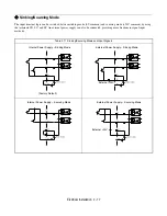
When using more than one Drive, be careful not to loop the ground wire. See Fig 2.4.

Fig 2.2  Ground Wiring Examples

Control Circuit Ground Terminals

The removable Drive control terminal card provides two ground terminals (marked TB3 and TB4) to accept the control wire
shield connection. The control wire shield should be connected on this end only, the opposite end should be isolated with 
electrical tape.

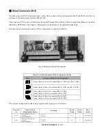
Table 2.6  Motor Cable Length vs. Carrier Frequency (C6-02)

Motor Cable Length

164 ft. (50m) maximum

328 ft. (100m) maximum

More than 328 ft.(100m)

Carrier Frequency

15kHz maximum

10kHz maximum

5kHz maximum

IMPORTANT

Grounding of the E7 enclosure and motor is required for proper system operation.

NO

OK

OK

NOT OK

Summary of Contents for E7 Drive

Page 1: ...ent reflects the most recent information provided by Yaskawa regarding these specific wire size tables This document is subject to change without notice The latest version of this document can be obta...

Page 2: ...chapter describes wiring terminals main circuit terminal connections main circuit terminal wiring specifications control circuit terminals and control circuit wiring specifications Terminal Block Conf...

Page 3: ...0 40 HP 480V and larger AC MP AM S6 V IG R M5 FM R RP S1 S4 SP S7 M4 V S3 SC S A2 M2 SN M6 AC A1 E G E G MC MB S5 M1 AC MA M3 S2 S AC MP AM S6 V IG R M5 FM R RP S1 S4 SP S7 M4 V S3 SC S A2 M2 SN M6 AC...

Page 4: ...T3 M4 13 3 1 5 14 2 1 22P2 3 R L1 S L2 T L3 1 2 B1 B2 U T1 V T2 W T3 M4 13 3 1 5 12 3 3 23P7 5 R L1 S L2 T L3 1 2 B1 B2 U T1 V T2 W T3 M4 13 3 1 5 10 5 3 25P5 7 5 R L1 S L2 T L3 1 2 B1 B2 U T1 V T2 W...

Page 5: ...39 2 4 0 X 2P 80 X 2P U T1 V T2 W T3 R1 L11 S1 L21 T1 L31 M10 199 22 5 3 0 X 2P 85 X 2P 3 M8 88 5 10 0 2 0 67 4 M10 199 22 5 2 0 X 2P 67 4 X 2P r l1 s l2 M4 12 4 1 4 14 2 1 2090 125 R L1 S L2 T L3 1...

Page 6: ...W T3 M4 13 3 1 5 14 2 1 14 2 1 45P5 7 5 R L1 S L2 T L3 1 2 B1 B2 U T1 V T2 W T3 M4 13 3 1 5 12 3 5 14 2 47P5 10 R L1 S L2 T L3 1 2 B1 B2 U T1 V T2 W T3 M4 13 3 1 5 10 5 5 12 3 5 49P0 4011 15 20 R L1...

Page 7: ...10 0 4 0 107 2 M12 347 39 2 2 0 67 4 r l1 s200 l2200 s400 l2400 M4 12 4 1 4 14 2 1 4110 200 R L1 S L2 T L3 1 M12 347 39 2 2 0 X 2P 67 4 X 2P U T1 V T2 W T3 R1 L11 S1 L21 T1 L31 M12 347 39 2 1 0 X 2P 5...

Page 8: ...5 C copper wire or equivalent IMPORTANT Determine the wire size for the main circuit so that line voltage drop is within 2 of the rated voltage Line voltage drop is calculated as follows Line voltage...

Page 9: ...n Circuit Terminal Functions 208 240Vac and 480Vac Purpose Terminal Designation Model CIMR E7U_ _ _ _ 208 240Vac 480Vac Main circuit power input R L1 S L2 T L3 20P4 to 2110 40P4 to 4300 R1 L11 S1 L21...

Page 10: ...to use recommended fuses circuit breakers See Appendix E may result in damage to the wiring Drive and or personal injury 2 Control power is supplied internally from the main circuit DC power supply f...

Page 11: ...uses circuit breakers See Appendix E may result in damage to the wiring Drive and or personal injury 2 Control power is supplied internally from the main circuit DC power supply for all Drives 3 Consu...

Page 12: ...than 100 2 480Vac Drives should have a ground connection with resistance of less than 10 3 Do not share the ground wire with other devices such as motors or large current electrical equipment 4 Alway...

Page 13: ...Digital Opera tor use shielded twisted pair wires and ground the shield to terminal E G as shown in Fig 2 3 Terminal numbers and wire sizes are shown in Table 2 7 Fig 2 3 Analog Input Terminal Configu...

Page 14: ...3 Wiring Checks After all wiring is completed perform the following checks 1 Is all wiring correct 2 Have all wire clippings screws or other foreign material been removed from the Drive enclosure 3 Ar...

Page 15: ...100 0 to 10 V 20 k A2 Multi function analog input 4 to 20 mA 100 0 to 10Vdc 100 H3 0 Function set by H3 09 4 to 20 mA 250 0 to 10 V 20k AC Analog common E G Shield wire optional ground line connectio...

Page 16: ...ble 2 9 DIP Switch S1 Name Function Setting S1 1 RS 485 and RS 422 terminating resistance OFF No terminating resistance ON Terminating resistance of 110 Factory Default OFF S1 2 Input method for analo...

Page 17: ...iguration for the analog output monitor signal type is listed below Table 2 10 Shunt Connector CN15 Configuration Options CN15 Analog Output Monitor Configurations Voltage Output 0 10Vdc for terminals...

Page 18: ...ng the terminals SN SC and SP An external power supply can also be connected providing more freedom in signal input methods Table 2 11 Sinking Sourcing Mode and Input Signals Internal Power Supply Sin...

Page 19: ...Electrical Installation 2 18 Terminal Connections Connections to Drive terminals are shown in Fig 2 6 Fig 2 6 Terminal Connections 24...

Page 20: ...trol circuit terminals 3 If using an optional external power supply ensure it is a UL Listed Class 2 power supply source 4 Use twisted pair or shielded twisted pair cables for control circuits to prev...

Page 21: ...Electrical Installation 2 20 Field Wiring Diagram Use this diagram to document field wiring It may be helpful to copy this page Fig 2 8 Field Wiring Diagram...

Reviews: