


2.2 Mechanical Installation
24
YASKAWA ELECTRIC
TOEP C710656 10B YASKAWA Power Regenerative Unit - R1000 Instruction Manual
■
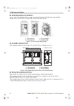
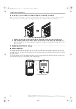
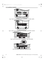
Single Regenerative Unit Installation
shows the installation distance required to maintain sufficient space for airflow and wiring. Install the
heatsink against a closed surface to avoid diverting cooling air around the heatsink.
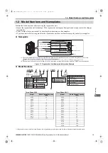
Figure 2.2
Figure 2.2 Correct Installation Spacing (Single)
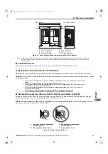
■
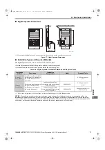
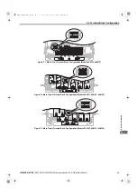
Parallel Mounting with Drive
When installing the regenerative unit beside a drive, mount the devices according to
Figure 2.3
Figure 2.3 Space Between Regenerative Unit and Drive (Parallel Mounting)
■
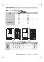
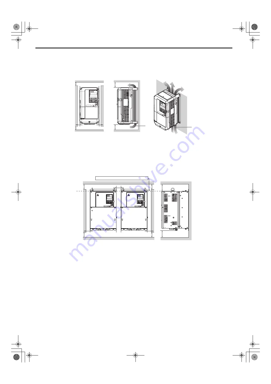
Side-by-Side Installation with Drive
Models 2A03P5 to 2A0028, 4A03P5 to 4A0028 can take advantage of Side-by-Side installation.
When installing the regenerative unit beside a drive, mount the devices according to
and set L8-35,
Installation Method Selection, to 1 (Side-by-Side Mounting).
When mounting regenerative units with the minimum clearance of 2 mm according to
, set parameter L8-35 to
1 while considering derating. Refer to
for details.
A – 50 mm minimum
C – 120 mm minimum
B – 30 mm minimum
D – Airflow direction
A – 50 mm minimum
C – 60 mm minimum
B – 30 mm minimum
D – 120 mm minimum
A
C
A
B
B
C
Side Clearance
Top/Bottom Clearance
D
D
A
A
A
A
B
C
Drive
Regenerative Unit
B
Line up the tops of the drive and regenerative unit.
Side Clearance
D
D
Top/Bottom Clearance
TOEP_C710656_10B_1_0.book 24 ページ 2015年1月8日 木曜日 午後8時55分


