


4.2
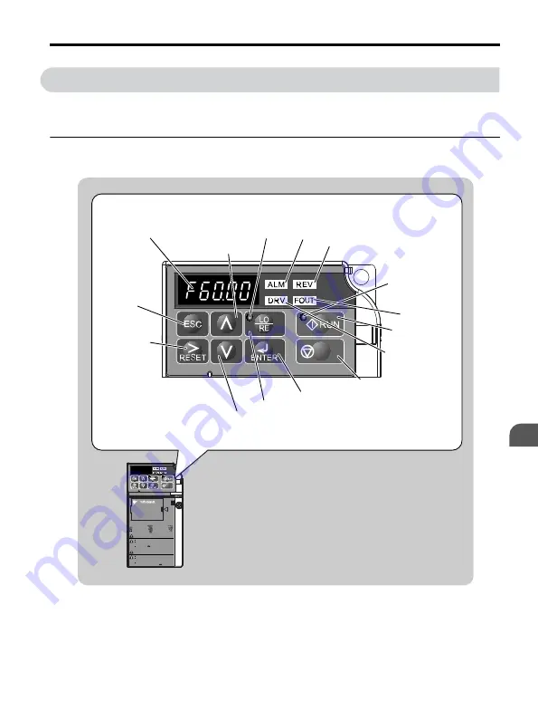
Using the Digital LED Operator
Use the LED operator to enter run and stop commands, display data, edit parameters, as well
as display fault and alarm information.
u
Keys, Displays, and LEDs
P
9
5
1
2
3
6
7
8
10
STOP
11
14
12
13
15
4
J1000
STOP
据え付け、運転の前には必ず取扱説明書を読むこと。
通電中および電源遮断後
5
分以内はフロントカバーを
外さないこと。
400V
級インバータの場合は、電源の中性点が接地
されていることを確認すること。( 対応)
けが、感電のおそれがあります。
危 険
Read manual before installing.
Wait 5 minutes for capacitor discharge after
disconnecting power supply.
To conform to requirements, make sure
to ground the supply neutral for 400V class.
Risk of electric shock.
WARNING
1
周波数指令
2
正転逆転選択
3
出力周波数
4
出力電流
5
出力電圧
:
:
:
:
:
:
:
:
:
6
モニタ
7
ベリファイ
8
セットアップ
9
パラメータ設定
4.2 Using the Digital LED Operator
YASKAWA ELECTRIC
TOEP C710606 26B YASKAWA AC Drive – J1000 Quick Start Guide
73
4
Start-Up Programming & Operation
http://nicontrols.com


