
18
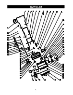
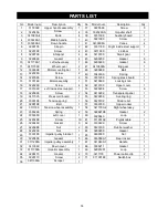
PARTS LIST
No Model num.
Description
Qty No Model num.
Description
Qty
1
3118099
Upper handle assembly
1
3320299-A
Impeller shaft
2
3220436
4
3
3410835-4
4
39
3331399
Auxiliary board
1
4
3330299-3
Middle handle
1
40
7
5
3330399-3
Down handle
1
41
6
3290135
Clip pin
2
42
3221099
Screw
7
3290799
4
43
3410999A
Vanes
4
8
S
3220199
Screw
hrapnel
4
44
3331199
Right inside steel support
1
9
3290699
Gasket
4
45
3411099
Link bar
1
10
46
Gasket
6
3290299
Gasket
8
11
47
1
3410799
Small gear
1
12
48
3290999
3290699
Ball
1
13
49
3340199
Spring
1
14
50
3410899A
Big gear
1
15
51
3331299
Spring press board
1
16
52
1
17
53
3410699
Locking knob
18
19
54
3410199
Upper cover
1
55
1
3220298
Screw
6
20
56
3410299
Transparent panel
1
21
57
3330799
Upper rocker
Rear rocker
3420299
Sealing ring
1
22
58
3411799-2
Right wheel assy.
1
23
59
32262198
2
24
60
3420102
Strain relief
1
25
61
31100199
Pigtail cable
3320640
Loop
Loop
1
26
62
1
27
63
Gasket
Gasket
1
28
64
3290299
Gasket
3330211
3420199
Rubber washer
1
29
65
3330499
Screw
1
30
66
3330599-1
3290599
Nut
1
31
67
3410499-1
Handle
1
32
68
1
33
69
32901251
1
34
70
35
71
36
37
38
3411799-1
Left wheel assy.
1
3411799C
Wheel cover
2
3330398
Motor mounting bar
1
3220299
Screw
2
3118199
3220598
Screw
2
2
M
3220999
Screw
Screw
Screw
otor assembly
1
3220299
Screw
4
3331099
Left inside steel support
1
3290198
Belt
1
3390198
Tension spring
1
3111198
Tension wheel assembly
1
3390298
Spring
2
3220298
10
3330999
Left cover
1
3
3220998
Nut
3290499
Gasket
2
3220236
Nut
1
1
5
3330198
Impeller pulley bracket
3220898
Gasket
1
3111298A
Impeller pulley assembly
1
3290173
2
3220110
2
3411535
Press cord board
1
1
3410399
Down cover
1
3225599
Screw
5
Gasket
1
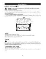
3411399A
Scraper
3111399A
Impellor assembly
2
31100199
1
3411135
Power cable clip
Switch box
Screw
Knob
Summary of Contents for 60-3982-0
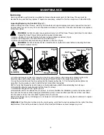
Page 14: ...14 Fig 8 Fig 8 Fig 8 ...
Page 17: ...17 PARTS LIST ...