


OPERATION
1. Make sure the rear tine tiller is on a flat, level surface.
ADD OIL TO ENGINE
3. Using a funnel, add oil up to the
FULL
mark on the dipstick.
(See engine manual for oil capacity, oil recommendation, and
location of fill cap.)
The engine is shipped without oil. Do not start the
engine before adding oil. Refer to your engine manual
for the proper oil gauge to use.
Gasoline is highly flammable and explosive. You can
be burned or seriously injured when handling fuel.
Use extreme care when handling gasoline.
Fill the fuel tank outdoors, never indoors. Gasoline
vapors can ignite if they collect inside an enclosure.
Explosion can result.
IMPORTANT: DO NOT OVERFILL!
This equipment and/or its engine may include
evaporative emissions control system components,
required to meet EPA and/or CARB regulations, that
will only function properly when the fuel tank has
been filled to the recommended level. Overfilling
may cause permanent damage to evaporative
emissions control system components. Filling to the
recommended level ensures a vapor gap required to
allow for fuel expansion. Pay close attention while
filling the fuel tank to ensure that the recommended
fuel level inside the tank is not exceeded. Use a
portable gasoline container with an appropriately
sized dispensing spout when filling the tank. Do not
use a funnel or other device that obstructs the view
of the tank filling process.
DO NOT OVERFILL. Check engine oil level daily and
add as needed.
1. The engine must be off and allowed to cool at least two minutes
before adding fuel.
2. Remove the fuel filler cap and fill the tank. (See engine manual
for fuel capacity, fuel recommendation, and location of fuel cap.)
ADD GASOLINE TO ENGINE
2. Remove the oil fill cap/dipstick
to add oil.
CLOSED
OPEN
3. Reinstall the fuel cap and tighten. Always clean up spilled fuel.
If the engine is hot,
closing the choke is not
necessary.
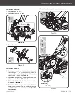
STARTING ENGINE
1. Open the fuel shut-off valve.
2. Move the choke lever to the
ClOSED position.
SLOW
FAST
OPEN
CLOSED
ON
OFF
12
Dual Rotating Rear Tine Tiller
»
Operator’s Manual
YT4565PM02 - 1704
Operation
|
1. Move the engine switch to the
On position.
ON
OFF
32850US25M102.indd 12
2017/3/27 10:22:05