background image

12

SECTION 7:  MAINTAINING YOUR LAWN MOWER

Cleaning Mower

The underside of the mower deck should be cleaned 
after each use to prevent any build-up of grass 
clippings, leaves, dirt, or other debris. 

NOTE:  We do not recommend the use of pressure
washers or garden hose to clean your unit. These may
cause damage to bearings or the engine. The use of
water will result in shortened life and reduce
serviceability.

Disconnect spark plug wire. Drain the gasoline from 
the lawn mower, or place a piece of plastic under 
the gas cap.

Tip the mower so that it rests on the housing. Keep 
the side with the air cleaner facing up. Hold the 
mower firmly.

Scrape and clean the underside of the deck with a 
suitable tool. Do not spray with water. 

Put the mower back on its wheels on the ground. If 
you had put plastic under the gas cap, make sure to 
remove it now.

Lubrication 

Blade Control Handle

Lubricate the pivot points on the blade control 
handle at least once a season with light oil. The 
blade control must operate freely in both directions. 

Wheels

Lubricate the wheels and bearings, if so equipped, 
at least once a season with light oil or engine oil. 
Also, if the wheels are removed for any reason, 
lubricate the surface of the pivot arm axle and the 
inner surface of the wheel with light oil. 

Rear Discharge Door

Lubricate the torsion spring and the pivot point on 
each end of the rear discharge door using a light oil. 
This will prevent rusting of the discharge door.

Engine Care

Follow the accompanying engine manual for detailed 
list and instructions. 

SECTION 8:  SERVICING THE MOWER

Blade Care

Periodically inspect the blade adapter for cracks, 
especially if you strike a foreign object. Replace when 
necessary.

Removing the Blade

Disconnect spark plug wire from spark plug.

Turn mower on its side making sure that the air filter 
and the carburetor are up.

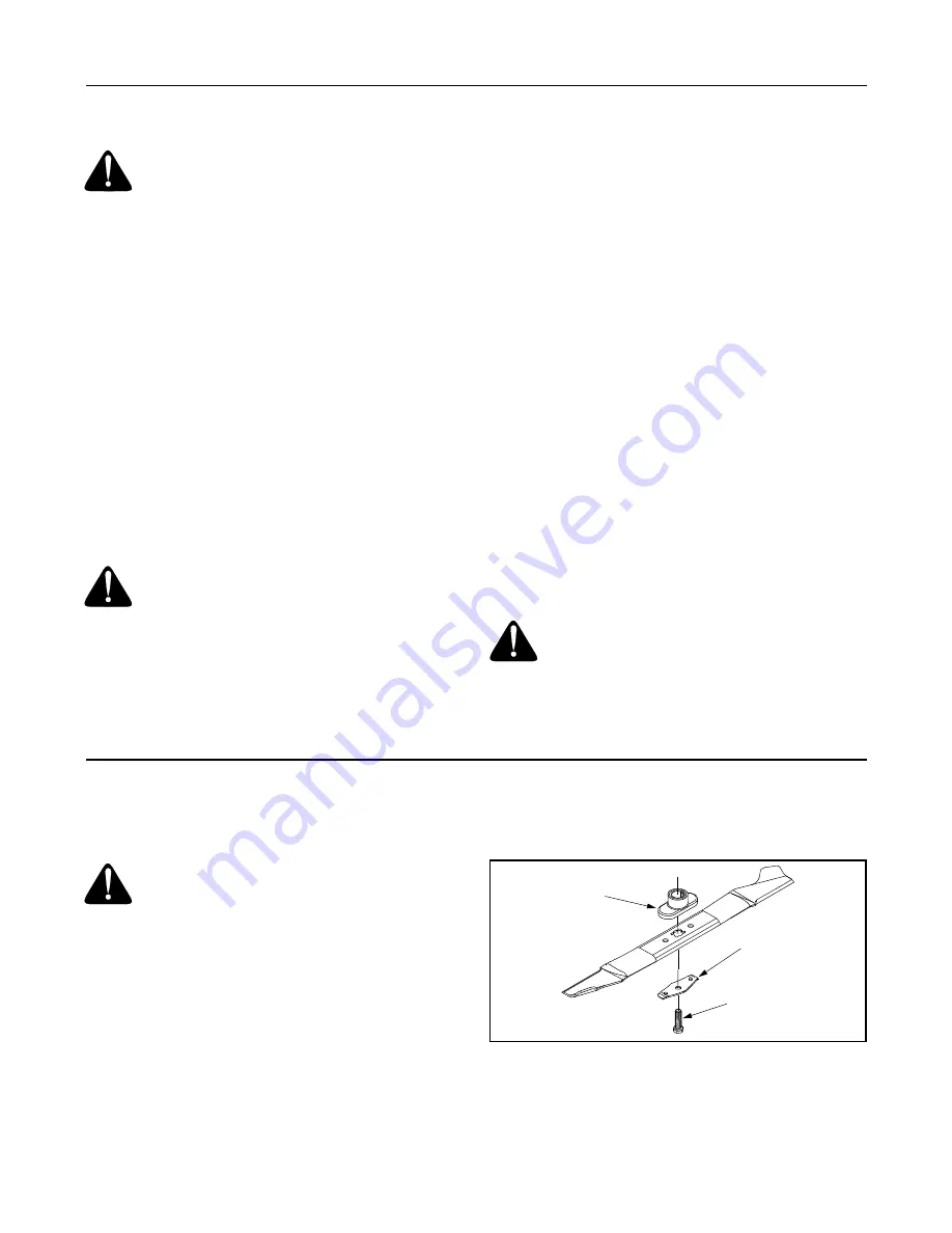
Remove the bolt and the blade bell support which 
hold the blade and the blade adapter to the engine 
crankshaft. See Figure 14.

Remove the blade and the adapter from the 
crankshaft.

Figure 14

Sharpening the Blade

The blade can be sharpened with a file or on a 
grinding wheel. Do not attempt to sharpen the 
blade while it is still on the mower.

WARNING: 

Always stop the engine and 

disconnect the spark plug wire before 
performing any maintenance work or 
adjustments on your lawn mower.

WARNING: 

Never tip the mower more than 

90 degrees in any directions and do not leave 
the mower tipped for any length of time. Oil can 
drain into the upper part of the engine causing 
a starting problem.

WARNING: 

Make sure to avoid muffler and 

surrounding areas while the mower engine is 
hot because temperature of these areas of the 
engine may exceed 150

o

 F.

WARNING: 

When removing the cutting 

blade for sharpening or replacement, protect 
your hands with a pair of heavy gloves or use a 
heavy rag to hold the blade.

Blade

Hex Bolt

Blade Bell

 Adapter

 Support

Summary of Contents for 549

Page 1: ...plicable local or state laws if any If a spark arrester is used it should be maintained in effective working order by the operator In the State of California the above is required by law Section 4442...

Page 2: ...help from the experts Choose from the options below Visit yardman com for many useful suggestions Click on Customer Support button and you will get the four options reproduced here Click on the approp...

Page 3: ...rotating parts or under the cutting deck Contact with the blade can amputate hands and feet 9 A missing or damaged discharge cover can cause blade contact or thrown object injuries 10 Many injuries oc...

Page 4: ...ooting or balance 2 Do not mow slopes greater than 15 degrees as shown on the slope gauge 3 Do not mow on wet grass Unstable footing could cause slipping Children Tragic accidents can occur if the ope...

Page 5: ...to improper performance and compromise safety 4 Mower blades are sharp and can cut Wrap the blade or wear gloves and use extra caution when servicing them 5 Keep all nuts bolts and screws tight to be...

Page 6: ...N T I N G A 1 5 S L O P E WARNING Do not mow on inclines with a slope in excess of 15 degrees a rise of approximately 2 1 2 feet every 10 feet A riding mower could overturn and cause serious injury If...

Page 7: ...pull back on the upper handle to raise the handle into the operating position See Figure 2 Make certain the lower handle is seated securely into the handle bracket assemblies Figure 2 Make sure that...

Page 8: ...came pre assembled proceed to the next section If it came unassembled follow the steps below to assemble it first before attaching to the mower Insert frame into grass bag with the black plastic side...

Page 9: ...Let mulch plug rest against the deck Operate mower without the grass catcher Refer to page 11 SECTION 4 KNOW YOUR LAWN MOWER Figure 12 Read this operator s manual and safety rules before operating yo...

Page 10: ...ld weather around 55 F or below prime five times Do not prime to restart a warm engine after a short shutdown Standing behind the mower depress the blade control handle and hold it against the upper h...

Page 11: ...ps from the weld pins on the handle brackets and remove the wing nuts and carriage bolts from the upper hole on the handle mounting bracket Press out on the legs of the lower handle and remove lower h...

Page 12: ...point on each end of the rear discharge door using a light oil This will prevent rusting of the discharge door Engine Care Follow the accompanying engine manual for detailed list and instructions SEC...

Page 13: ...ne storage instructions Coat mower s cutting blade with chassis grease to prevent rusting Store mower in a dry clean area Do not store next to corrosive materials such as fertilizer SECTION 9 TROUBLES...

Page 14: ...ARTS LIST FOR MODEL 549 1 6 7 8 9 10 11 12 13 18 19 2 49 50 55 56 57 58 59 61 62 40 47 54 53 51 52 65 37 42 40 39 36 15 35 22 31 32 16 25 29 26 49 30 49 23 49 21 20 34 43 45 64 29 24 49 33 17 36 5 14...

Page 15: ...82 5004A Rear Baffle RH 31 782 5003 Rear Baffle LH 32 710 1017 Tap Screw 1 4 14 x 625 33 712 3005 Flange Lock Nut 3 8 16 34 710 0703 Hex Carriage Screw 1 4 20 35 687 02033 Handle Bracket RH 687 02031...

Page 16: ...tments and normal deterioration of the exterior finish due to use or exposure d Service completed by someone other than an authorized service dealer e MTD does not extend any warranty for products sol...

Reviews: