background image

EF494T OM 

15 

AFTER SALES SERVICE AND WARRANTY

After sales service 

If your tractor is not working normally, refer to the 
troubleshooting section in this manual. You can also 
consult with your service representative.  
 
Information needed when asking for service: 
 

  Model name and serial number (A) of your tractor.  

  Engine type number (B) 

  Operating conditions. What type of work was being 

performed when the problem occurred? 

  How long have you used your tractor? (total hours of 

operation) 

  Any other information about the problem that has 

occurred. 

Availability of spare parts 

Maintenance parts and spare parts will be available for 
10 years after the production of this tractor series has 
been discontinued. However, special parts will be 
available subject to consultation. Yanmar may be able to 
supply a particular part after the normal supply period. 
 

(A) Tractor serial number 
(B) Engine type number 


(A) 


(B) 

PURPOSE OF THIS MACHINE 

This machine is designed to be operated with a various 
implement for particular tasks and for pulling a trailer in 
a variety of agricultural operations. Other use or 
modification is prohibited. 
 
Orientation and Position Marks  
 
A right-hand and Left-hand side of the machine is 
determined by facing in the direction of the machine 
forward travel. 


Summary of Contents for EF-494T

Page 1: ...OPERATOR S MANUAL DIESEL TRACTOR EF494T Original instructions en...

Page 2: ...erate or service this machine until you have first read and understood all of the applicable Safety Instructions that are set forth in this Manual The failure to comply with all relevant Safety Instru...

Page 3: ...the possibility of personal injury and carefully read the messages that follow 2 Signal Words The signal words DANGER WARNING CAUTION are used with the safety alert symbol 1 DANGER indicates an immine...

Page 4: ...13 Position control 41 14 Using differential lock 41 15 Loading and unloading 42 16 Adjusting wheel tread 42 17 Hydraulic output 44 18 Using 3 point link 45 19 Adjusting top link 46 20 Mounting gener...

Page 5: ...belt 69 17 Adjusting tow in 69 18 Replacing fuse 70 19 Checking tires 71 20 Color of exhaust gas 71 TROUBLESHOOTING 72 1 Engine parts 72 2 Clutch brake and related parts 73 3 Hydraulic system 73 4 Ele...

Page 6: ...or s manual should be considered a permanent part of the tractor and should remain with the tractor Know the positions and functions of all controls and the meaning of any identification symbols on yo...

Page 7: ...welding bending grinding or cutting them If any component of the ROPS is damaged or involved in a rollover incident replace it with a complete new cage Do not attempt to repair the original one Damag...

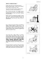
Page 8: ...loor To attach or remove an implement refer to the implement and tractor manufacturer s manuals for the proper procedures To unhitch an implement move to a level area lower the implement to the ground...

Page 9: ...ecurely while warming it up Only start the engine from the operator s seat Never start the engine while standing on the ground Before you start the engine 1 Sit in the operator s seat and adjust the s...

Page 10: ...ents Always use the handrails and steps and face the tractor when getting on and off Never use control levers as a handhold and never step on foot controls when getting on and off Do not get on the tr...

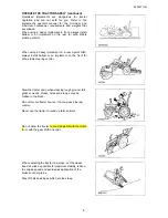
Page 11: ...ays install ballast or an implement on the front for safe stable steering control Slow the tractor down when crossing rough ground tall grass or weeds Rocks holes and stumps may be hidden in the brush...

Page 12: ...ove the drawbar Doing so could cause the tractor to tip over backward Only attach items to be pulled to the drawbar Use care when pulling loads or installing a heavy implement 1 Only use approved hitc...

Page 13: ...PTO speed matches the implement s required PTO speed Do not drive or operate the implement beyond the tractor s PTO speed Stop the engine and be sure the PTO has stopped moving before 1 Connecting or...

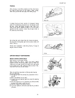
Page 14: ...ith the least braking possible Do not coast downhill Do not stop or start suddenly when going uphill or downhill When loading or unloading the tractor onto a vehicle use care as follows 1 Use a strong...

Page 15: ...concerning towing Towing is illegal in some countries AFTER THE DAY S OPERATION PARK THE TRACTOR SAFELY Park tractor on a firm level surface When parking the tractor couple the brake pedals together...

Page 16: ...f fuel is spilled wipe it up immediately Install the fuel tank cap securely after refueling Be sure there is plenty of ventilation before charging the battery Gas produced while charging the battery i...

Page 17: ...useful working life Do not use substitute parts that may not meet the strength and design requirements or may not fit the tractor Do not use repair parts not approved by YANMAR Remove the radiator cap...

Page 18: ...by escaping fluid see a doctor at once Serious infections and other problems can develop if proper medical treatment is not administered immediately Disconnect the battery ground cable before working...

Page 19: ...of the governmental agency for the proper disposal of hazardous materials such as engine oil diesel fuel engine coolant and machine fluid grease NEVER dispose of hazardous materials irresponsibly by d...

Page 20: ...urred Availability of spare parts Maintenance parts and spare parts will be available for 10 years after the production of this tractor series has been discontinued However special parts will be avail...

Page 21: ...2 The electrical fuses are in the engine compartment Use of fuse other than a correctly rated one way may cause damage to the electrical system Replace the blow fuse with a new fuse of the same ampera...

Page 22: ...e the transmission case and create a dangerous situation Aluminum cases Reference The bolt length B in the case must be 2 0 times the diameter of A For casting metal cases rear axles etc The bolt leng...

Page 23: ...speed too much or carry any more load than is necessary 3 Operate the tractor only after the engine has warmed up sufficiently 4 Slow down on a rough road or on a slope 5 Check the tightness of the wh...

Page 24: ...axle bracket 5 Front wheels 6 Steering wheel 7 Safety frame ROPS 8 Tail lamp 9 Fuel tank 10 Rear wheel 11 Hydraulic stop slow return valve 12 Sub step 13 Operator s seat 14 Top link 15 Lower link 16...

Page 25: ...ake lever 5 Operator s seat adjusting pin 6 Range shift lever 7 Front wheel drive lever 8 Seat belt 9 Main switch 10 Accelerator lever 11 Main shift lever 12 Brake pedal 13 Accelerator pedal 14 Differ...

Page 26: ...ire caution 4 198163 65350 Label danger rotate shaft 5 198283 65651 Label Thailand only 6 Label tractor ID 7 Label engine ID 8 1A7781 65560 Label speed 9 1A6150 93151 Label caution cover 10 198163 659...

Page 27: ...e engine is stopped the engine lubricating oil lamp and charge pilot lamp turn on OFF The electric current is shut off The key can be removed Accelerator lever A Accelerator lever B Engine slow speed...

Page 28: ...running forward and move the lever rearward for running reverse Lift up the lever and move it to desired position When shifting the lever be sure to depress clutch pedal and that tractor stops comple...

Page 29: ...or topple A Connector link for traveling on road B Left Brake C Right Brake Left and right pedals can be operated separately For a sharp turn in the field depress the brake in which direction you wan...

Page 30: ...t make an intended turn and an accident may result A Differential lock pedal B Release lock C Press to activate differential lock This pedal makes both side wheels to turn as a consolidated form if on...

Page 31: ...st position A Upper B Upper stopper C Position control lever D Knob Adjusting the stopper Move the knob to a required position Preventing an implement from dropping Set the lever as illustrated Hydrau...

Page 32: ...ks Head light switch Headlights turn on when key switch turns on Turn head light switch clockwise to turn on head lights B Light switch OFF Headlights turn off LB Headlights turn on with low beam HB H...

Page 33: ...This lamp lights when the main switch is turned on and goes off when the engine starts If the lamp lights during engine speed suspect an abnormality in the lubrication circuit Stop the engine immedia...

Page 34: ...en seat belt while operating the tractor with the ROPS Do not use the seat belt if the tractor does not have the Roll over Protective Structure ROPS A Buckle B Tongue Connect both segments of the belt...

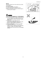
Page 35: ...her vehicles or people Otherwise the tractor can collapse and cause an unexpected accident When accessing beneath an implement close the hydraulic valve completely to stop the oil flow Otherwise the i...

Page 36: ...to look into Deformed parts damages wear Air pressure of tires wear of tires Wear of various parts loosened bolts and nuts Loosened bolts and nuts of the tire rims and disks Fuel oil amount and leak d...

Page 37: ...ir filter Tension or damage of cooling fan belt Check the radiator grill and engine room for dust Check electrical wiring for wear of sheath and loose joints 4 Sitting on the operator s seat Effect an...

Page 38: ...OM 33 Play in the steering wheel A Play 20 50mm Effect and play in the clutch pedal A Play 15 25mm 5 Start the engine Check for abnormal sound Color of exhaust gas A What color Function of lamps and...

Page 39: ...evers and controls are within the reach for safe operation Negligence will cause a serious injury Do not start the engine in a closed room Start the engine outdoor where the good ventilation is availa...

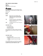
Page 40: ...cock A Fuel cock open B Fuel cock close 2 Put the main and range shift levers reverse lever and PTO shift lever in the N position 3 Set the position control lever in LOW 4 Put the accelerator lever i...

Page 41: ...ne running unloaded at 1200 1500 RPM for about 2 minutes to prevent damage 4 Raising or lowering implement Adjust the position control lever back and forth to raise or lower the implement A Position c...

Page 42: ...1 Check that the left and right brake pedals are tied together with the connector 2 Set the engine speed around 1500 rpm with the accelerator lever 3 Move the position control lever to Upward to lift...

Page 43: ...draulic device in the upper position adjust the upper stopper and move the position control lever to the stopper A Position control lever B Upper stopper Adjust the traveling speed with the foot accel...

Page 44: ...should be changed after reaching a highest point on the slope To stop on the slope lock the parking brake lever 9 Power steering CAUTION The steering wheel is easily rotated when the tractor is runnin...

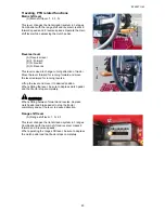
Page 45: ...lower any implement After the rear wheels are on the ridge A you can lift the implement A Ridge 11 Setting an adequate speed 9 forward speeds and 9 reverse speeds are available by the combination of m...

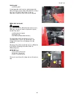
Page 46: ...plement adjust the position control lever until it stops in a wanted position Fix it with the lowest stopper 14 Using differential lock WARNING Disengage the differential lock before making a turn Oth...

Page 47: ...t for loading forward shift for unloading Fasten the tractor firmly with the rope If the tractor falls off the truck it may be damaged or injure someone 1 Prepare the gangplank of sufficient strength...

Page 48: ...s to check for loose nuts and bolts on the wheels If they are loose retighten them to the specified torque When wheel tread width was changed check the bolts and nut tightening after the first 10 hour...

Page 49: ...king and plugs A Hydraulic output plug NOTE 3 point rear hitch implement cannot be controlled by position control lever while stop slow return valve is closed Double action cylinder 1 Remove the plug...

Page 50: ...kward A Lower link B Lift link mounting holes 2 Fix the check chain on the chain bracket and the lower link mounting holes rearmost Foremost holes are used for coupling the lift link A Check chain bra...

Page 51: ...se A or B or C depending on the implement 19 Adjusting top link Loosen the lock nut for the top link and turn the turnbuckle to adjust the length of the top link When an implement is not used hang the...

Page 52: ...lock nut and turn the turnbuckle Lock the implement with the lock pin 5 Loosen the lock nut of the top link and turn the turnbuckle for adjustment Fix the implement in the top link mounting position...

Page 53: ...ement on a flat ground using a safe method Use the lighting during nighttime works When a heavy implement is mounted on the tractor apply a counterbalance to maintain a balanced condition Before leavi...

Page 54: ...rawbar hitch is provided A Draw bar hitch B Fixing pin Combined PTO drive and traction For a combined operation of PTO drive and traction the length from the edge of the PTO shaft to the mounting posi...

Page 55: ...maged frame should be replaced as a complete set Partial repair may lead loss of safety level Folding in safety frame 1 Loosen bolts B and remove bolts A 2 Push down the frame backward 3 Install bolts...

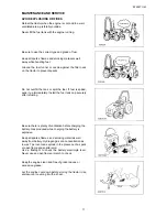
Page 56: ...You may be pulled into the machine and be injured Wait until the muffler and the engine get cool before starting checks and maintenance NOTE Be careful not to spray water on electrical parts Water inf...

Page 57: ...with the locking knob 3 Checking and supplying fuel DANGER Never smoke during re fueling Never use a bare lamp light during re fueling After adding fuel be sure to fasten the fuel cap and clean off t...

Page 58: ...oil Otherwise moisture will develop in the tank and cause rust Put the fuel cock in the CLOSE position 4 Fully charge the battery It is recommended to detach the battery from the tractor and keep it...

Page 59: ...ncing checks and service Remount the covers which have been removed for maintenance The revolving parts may catch a person nearby leading to a serious injury Periodic inspection and maintenance in off...

Page 60: ...x x x x x x x Battery liquid level Check before every work Battery liquid gravity x x x x x x Fuel piping connections x x x x x x x x x x x x Rubber hoses Power steering x x x x x x x x x x x x Radiat...

Page 61: ...il while the engine is warm or running A fire may occur CAUTION Never add oil just after stopping the engine You may be burned Engine oil Check Draw out the oil gauge on the right side of the engine a...

Page 62: ...easy if the transmission case is warm Add the new oil through the supply port on the rear part Transmission oil is commonly used with hydraulic oil and power steering oil Use Yanmar transmission fluid...

Page 63: ...r TF500A transmission fluid or carrier red 80B or equivalent for front axle oil A Center drain plug B Gear case drain plug 5 Replacing oil filter elements Engine oil element Replace the engine oil ele...

Page 64: ...evel in the sub tank whether water is between FULL and LOW marks If water is insufficient remove sub tank cap and add clean water Be sure to close the sub tank cap firmly A Sub tank B Sub tank cap C U...

Page 65: ...water gets in the plunger and barrel Drain the water accumulated in the water separator regularly every 100 hours or shorter if much water in the bowl 1 Remove the cover A 2 Turn the fuel cock 2 to b...

Page 66: ...ndition clean it every 100 hours and replace it every 1000 hours Even before the said intervals replace it every year Cleaning air cleaner element 1 Open the bonnet 2 Remove the sub tank 3 Open the li...

Page 67: ...it add distilled water as high as the upper limit A Battery B Upper limit C Lower limit NOTE Excessive battery fluid may overflow during recharging damaging the metallic parts of the tractor Add disti...

Page 68: ...ION Aged or damaged pipes are subject to fuel leak which will cause a fire Check for a leak and replace the pipe with new one Check the power steering pipes fuel pipes and radiator hoses for leak or l...

Page 69: ...greasing condition at each point Grease up after a work on a muddy field As a general rule grease up various points at intervals of 50 hours A Brake pedal shaft B Tie rod C Power steering rod D Front...

Page 70: ...d as the right picture shows A Band B Bolt C Collar D Front shaft cover 4 Turn over the rubber boots E as the right illustration shows 5 Slide the coupling F backward as the right illustration shows B...

Page 71: ...ight illustration shows 4 Slide the coupling F frontward as the right illustration shows Be careful not to lose ball G 5 Apply enough multipurpose Grease to six balls G 6 Turn back rubber boots E to t...

Page 72: ...amount of play otherwise an accident can result Depress the brake to see a required play of 30 40 mm is available and if the left and right pedals work together If not adjust the turnbuckles behind th...

Page 73: ...A Play 15 25 mm B Turn buckle 15 Adjusting steering wheel WARNING Check a play for the steering wheel It should be within a tolerable range Otherwise an accident may occur Turn the steering wheel sli...

Page 74: ...ator to adjust the belt tension If the belt still slips after full shift of the alternator replace the belt with a new one Check the new belt at intervals of 50 hours A Alternator B Alternator fasteni...

Page 75: ...hich shuts off the electrical circuit when an excessive current flows Fused condition can be checked by the changed color of the outer sheath A Fuse box START Starter motor 5A WORK Working light 5A TU...

Page 76: ...e kg cm2 Front tire 2 4 Rear tire 2 0 Fastening torque Front and rear Fixing bolts for wheel and axle shaft 186 N m 19 kgf m Excessive Standard Insufficient 20 Color of exhaust gas The color of exhaus...

Page 77: ...ed in the fuel Remove water and replace with light oil Jet nozzle clogged Replace or repair the nozzle Clogged fuel filter Clean or replace the filter element Engine overheating Lack of cooling water...

Page 78: ...r Have it repaired at your service representative Impossible to lower the attachment implements Hydraulic stop slow turn valves are close Open the hydraulic stop slow turn valves Dusty control valve O...

Page 79: ...rward km hr 30 8 Tire Front 8 18 6 Rear 13 6 26 8 Rear PTO Type Transmission PTO PTO shaft SAE1 3 8 inch 35mm 6 spline Speed rpm 568 769 at rated engine speed Hydraulic Type Position control Hitch 3 p...

Page 80: ...on or failure that results from use of an unapproved implement Lower link end maximum lifting capacity Implement weight and size Maximum drawbar load Trailer loading weight maximum capacity W0 W1 W2 W...

Page 81: ...EF494T OM...

Reviews: