9
Initial Operation
1.
Gradually open the inlet valve (make sure that the outlet valve, if
installed, is open).
2.
Check the filter assembly and its connections for leaks.
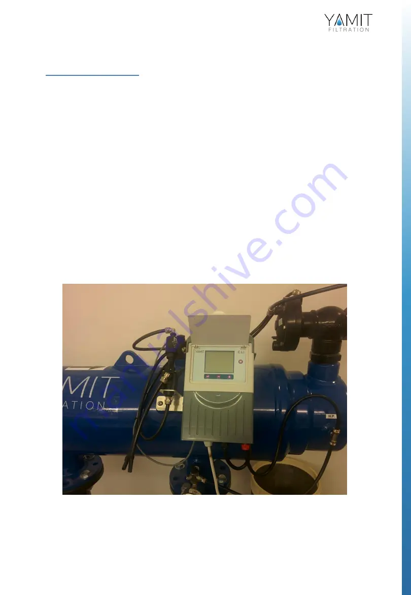
Perform a flushing cycle manually by pushing the test button located on
the outside of the control box (See Figure 3).
3.
Verify that the hydraulic piston fully extends during back flush.
4.
Verify that the hydraulic flushing valve closes after 10 seconds.
5.
When the filter is clean, verify that the differential pressure between
inlet and outlet does not exceed 0.1 bar.
6.
Check that the differential pressure is set to 7 psi or 0.5 bar (5 meter) in
the controller (see Appendix 1).
Figure 3: Control Unit
AF800N
Summary of Contents for AF800N Series
Page 17: ...17 Figure 8 Fine Screen Assembly Removal Replacement AF800N ...
Page 19: ...19 Figure 9 Dirt Collector Removal Replacement AF800N ...
Page 21: ...21 Figure 10 Periodic Checks AF800N ...
Page 27: ...27 8 IPB 8 AF800N ...
Page 36: ...36 DC MODEL GALSOL DC AF800N ...
Page 38: ...38 9 2 Control Loops Schematic Drawing ONE VALVE hydraulic Scheme DC1 10 CTRL AF800N AF800N ...
Page 39: ...39 ONE VALVE hydraulic Scheme AC1 10 CTRL AF800N AF800N ...


