background image


17 

4. INSTALLATION PROCEDURES 

Installation Procedure 


2. Hose connection to the external device 

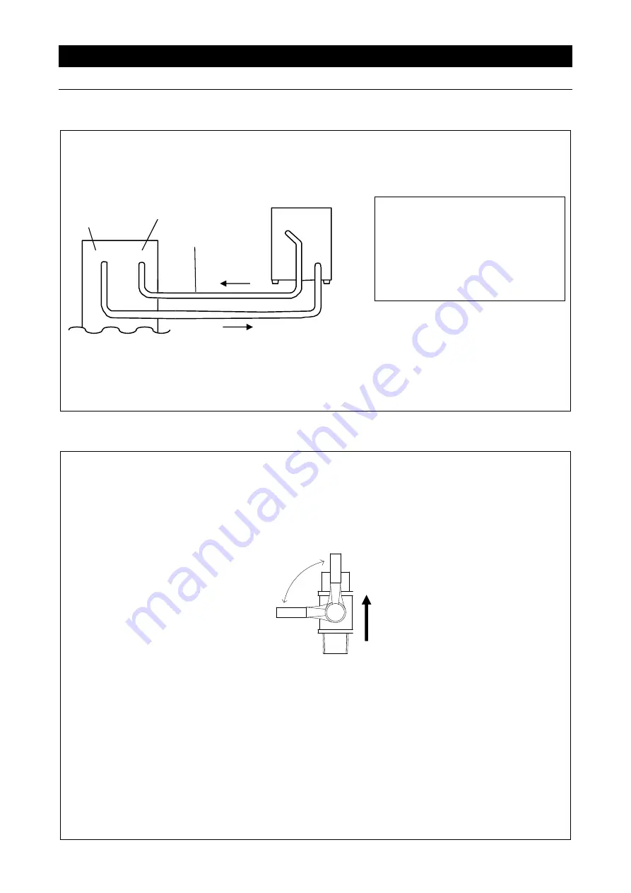
When a connection between unit and hose is made, connect to an external device as shown in the 
figure. Rotatable connector on the connection port allows free change in the direction. Adjust the 
direction so that the hose does not bend when connected to an external device. 


 As the standard specifications, 

both IN/OUT can be connected 
with fittings for a rigid hose with 
10 mm O.D. and for a flexible 
hose with 9 mm I.D. when 
connected with included 
accessory. 

(Hoses are not included) 


 Check the pump head of the circulation pump (0.1MPa 

 10 m) from the specification column and 

select a hose with sufficient pressure resistance. Use a hose clamp to secure the hose. 

See "List of Options" (P.37). 

Do not operate unit with the external circulation path shut. 


3. External circulation path 

A variety of optional accessories are available to suit the piping system of external device and for a 
wide range of uses. 

Where the optional flow rate valve is installed (P.36 “List of options”), be sure to open it whenever 

running the circulation pump. Do not excessively restrict flow.    Do not shut the external circulation 
path completely. Doing so may cause damage to the circulation pump. 

Ensure the minimum flow rate of 1 L/min. 
 

 Operation of flow rate valve (optional) 


Be sure that circulation lines are the minimum required lengths. Cooling efficiency is decreased 
while flow resistance increases in relation to longer circulation line length.   
See "11. SPECIFICATIONS" (P.33) for pump capacity. 

Be sure that the circulating water line forms circulation path. Do not connect circulation lines to 
gas or water plumbing lines. 

Check the specifications of the external devices (required flow rate, allowable pressure of piping) 
in order to avoid accident or equipment malfunction. 

Do not connect CF series unit to external devices with supplemental powering mechanisms. 

Always change the flow rate slowly. A sudden change in the flow rate may shorten the life of the 
circulation pump. 

Be careful not to let the circulating water flow backward when connecting to an external device 
located higher than CF unit. Backflow may cause overflow from the water reservoir. 

CF unit 

External device 

(closed system) 

Hose 

Discharge 

port


(OUT)


(IN)


Return port


Open 

Close 

Flow of circulating water 

Flow rate valve 

Summary of Contents for Neocool CF302L-A

Page 1: ...hoosing CF302L A Neocool Circulator from Yamato Scientific Co Ltd For proper equipment operation please read and become thoroughly familiar with this instruction manual before use Always keep equipment documentation safe and close at hand for convenient future reference Warning Read instruction manual warnings and cautions carefully and completely before proceeding ...

Page 2: ......

Page 3: ...Operation procedure 19 User Setting 20 Calibration offset 21 Auto resume function 22 Selection of circulation pump operation at temperature upper limit alert 23 LED brightness setting 24 6 HANDLING PRECAUTIONS 25 Warnings and Cautions 25 7 MAINTENANCE PROCEDURES 27 Inspection and Maintenance 28 8 EXTENDED STORAGE AND DISPOSAL 29 Extended Storage Unit Disposal 29 Disposal Considerations 29 9 TROUBL...

Page 4: ...13 OPTIONAL ACCESSORIES 36 List of Options 36 14 WIRING DIAGRAM 39 CF302L A 39 15 REPLACEMENT PARTS LIST 40 16 LIST OF HAZARDOUS SUBSTANCES 41 17 STANDARD INSTALLATION MANUAL 42 ...

Page 5: ...1 1 SAFETY PRECAUTIONS Explanation of Symbols ...

Page 6: ...ast Hazard Caution Water Only Caution Shock Hazard Caution Burn Hazard Caution Do Not Heat Without Water Caution May Leak Water Caution Toxic Chemicals RESTRICTION General Restriction No Open Flame Do Not Disassemble Do Not Touch ACTION General Action Required Connect Ground Wire Level Installation Disconnect Power Inspect Regularly ...

Page 7: ...tion may result Never connect ground wire to telephone grounding lines or to lightning conductor rods Fire or electric shock may result Never insert multiple plugs into a single outlet Doing so may result in power cable overheating fire or drop in voltage Connect to grounded outlet Grounded outlet When no ground terminal is found Contact original dealer of purchase for location specific electrical...

Page 8: ...lities may cause fire or electric shock resulting in serious injury or death Always connect power cable to appropriate facility outlet or terminal Keep power cable connection clean Buildup of dust on the connection may cause fire and or electric shock DO NOT disassemble or modify equipment Never attempt to disassemble or modify unit Doing so may cause malfunction fire electric shock or personal in...

Page 9: ...rstorm turn OFF ELCB and disconnect power cable immediately A direct lightning strike may cause equipment damage fire or electric shock resulting in serious injury or death Turn OFF ELCB in case of power failure Operation stops when power failures occur For added safety however turn OFF ELCB in the event of a power failure ...

Page 10: ...dicate the numbers listed in the List of Residual Risks in this manual For details of individual residual risks see the List of Residual Risks Contact us if the caution signs are no more visible because nameplate is peeled off or texts are eliminated We will send you a new nameplate for charge Rating label 2 3 6 7 10 12 14 16 ...

Page 11: ...of people and an appropriate work method when carrying out manually 13 2 WARNING Fire Electric shock Choose an appropriate installation site 13 3 CAUTION Injury Install unit on a level surface 13 4 CAUTION Injury Take appropriate safety measures when installing 13 5 WARNING Fire Install equipment in a well ventilated place 14 6 WARNING Fire Electric shock Install in a dry location 14 7 WARNING Exp...

Page 12: ...OFF ELCB immediately when an abnormality occurs 3 14 WARNING Burn DO NOT touch hot cold surfaces 4 15 CAUTION Fire When unit stops operation due to power failure etc be sure to confirm the state of unit at the time of power recovery 25 16 WARNING Injury DO NOT climb or place any objects on top of equipment 4 17 WARNING Fire DO NOT operate equipment during thunderstorms 5 18 CAUTION Burn Injury ALW...

Page 13: ...NG Burn Injury Perform inspections and maintenance when unit and circulating water is at room temperature 27 21 WARNING Fire Electric shock NEVER disassemble or modify unit 27 Extended storage disposal No Degree of risks Risk description Protective measures taken by the user Relevant page s 22 WARNING Fire Electric shock Turn OFF ELCB and disconnect power cable from facility outlet or terminal 29 ...

Page 14: ...luded Drip tray Please prepare separately Hose clamp included Rubber foot Drain hose Drain plug Condensate drain hose Power cable 2 m with plug 115 V AC Discharge port Return port Rigid hose coupling with 10 mm O D or flexible hose coupling with 9 mm I D When attaching the supplied hose nozzle One touch connector L type can rotate freely Hose nozzle included One touch connector L type Discharge Re...

Page 15: ...11 2 COMPONENT NAMES AND FUNCTIONS Circulation System Pt Return IN Discharge OUT Drain plug Circulation pump Water reservoir Drain Temperature sensor Rc3 8 Rc3 8 Cooling coil ...

Page 16: ...ng circulating operation Refrigerator lamp Hereinafter Ref lamp Flashes when the compressor delay timer operates Goes out when the timer ends after about three minutes Illuminates while refrigerator is running Synchro lamp Not used for this unit Power switch Turn ON OFF power Display Characters All characters displayed when making settings are defined as follows Character Letters Description CAL A...

Page 17: ... least 50 cm Operating unit in a location with poor ventilation under a laboratory table etc exhaust heat may be trapped and the cooling capacity may be greatly degraded In this case use an exhaust unit to dissipate the heat around unit Estimated volume of exhaust is as follows Approximate amount of waste heat kW 0 6 Approximate exhausts m3 min 2 0 Use cargo handling equipment for transportation a...

Page 18: ...tion such as connecting unit to a dedicated power source Connecting multiple cables using a branch outlet or extension cord will cause voltage to drop leading to degraded temperature control or malfunction Power cable terminal processing Standard Cable end processing 3 core 2 0 mm2 1 With a plug The length of power cable is about 2 m 1 Nominal cross sectional area of conductor Install equipment in...

Page 19: ...der when evaporated Degraded unit performance and or pump overload may be caused by using heavy or viscous circulating water such as FluorinertTM GaldenⓇ etc Do not use pure water as circulating water It may corrode the copper in the wetted part Do not use corrosive liquid or circulating water that generates corrosive substances when heated FluorinertTM etc When using a mixture of antiseptic agent...

Page 20: ...ist of Options P 37 When using rigid hose with 10 mm O D Put the supplied insert sleeve into rigid hose and push the hose straight to the end while holding the connection port with hand Failure to use the insert sleeve may lead to water leakage To remove the hose pull out the hose with the ring of the connection port pushed in When using a flexible hose with 9 mm I D 1 Connect the flexible hose se...

Page 21: ...pen it whenever running the circulation pump Do not excessively restrict flow Do not shut the external circulation path completely Doing so may cause damage to the circulation pump Ensure the minimum flow rate of 1 L min Operation of flow rate valve optional Be sure that circulation lines are the minimum required lengths Cooling efficiency is decreased while flow resistance increases in relation t...

Page 22: ...ir cover Do not open the cover unless otherwise necessary to prevent dust foreign object etc from entering the reservoir Use caution not to let circulating water spill over unit Electric leakage or electric shock may result if the circulating water comes into contact with the electrical components When circulating water spills on the control panel wipe it dry with a clean dry cloth 5 Installation ...

Page 23: ...s off after about three minutes Refrigeration unit Stop Ref lamp indicates the operating state of the refrigerator OFF Standby ready for operation ON In operation Flashing In preparation It takes about three minutes from the refrigeration stop to restart operation for protecting the refrigerator 4 Start circulation Press key for one second Pump lamp ON Circulation pump Run To stop Press key again ...

Page 24: ...e temperature displayed on the control panel Offset function can correct to either the positive or negative side of the entire unit temperature range Setting range 5 0 to 5 0 C Default setting is 0 0 P 21 Auto resume function Select operation for the time power is restored OFF Unit goes into idle at power recovery ON Unit automatically reverts to status just before power loss and begin operation o...

Page 25: ...mpensate against the actual temperature deficiency of 2 C If the initial temperature reading was 20 C it will read 18 C after offset calibration and be brought into agreement with actual temperature 1 Enter user setting Turn power switch ON and press key for three seconds while temperature reading is on the screen Unit enters user setting 2 Change offset value 1 Select CAL using the keys Temperatu...

Page 26: ...d press key for three seconds while temperature reading is on the screen Unit enters user setting 2 Change the Auto resume setting 1 Select Pon using the keys Temperature display Pon flashes 2 Press key Temperature display Current set value flashes 3 Use the keys to alter the setting 4 Press key to finalize Temperature display Set value is shown for about one second After completion the screen ret...

Page 27: ...d press key for three seconds while temperature reading is on the screen Unit enters user setting 2 Change the pump operation setting 1 Select PUP using the keys Temperature display PUP flashes 2 Press key Temperature display Current set value flashes 3 Use the keys to alter the setting 4 Press key to finalize Temperature display Set value is shown for about one second After completion the screen ...

Page 28: ... setting 2 Select the LED brightness level 1 Select dSP using the keys Temperature display dSP flashes 2 Press key Temperature display Current set value flashes 3 Use the keys to alter the setting 4 Press key to finalize Temperature display Set value is shown for about one second After completion the screen returns to step 1 3 Exit user setting After completing the setting press and hold key for t...

Page 29: ...servoir before use Unit has been cleaned at the time of shipment However when unit is used for the first time or has been in storage for a long period of time Fill the reservoir with tap water and drain to clean the reservoir and water lines Overnight and extended storage Whenever unit is not in operation stored overnight or put in storage always turn ELCB OFF and disconnect power cable Drain circ...

Page 30: ...ow rate of circulating water keeps at least 1 L min Refrigerator abnormal stop If room temperature and liquid temperature are high or the intake dust filter is clogged increasing the load of the refrigerator The refrigerator high pressure cut off switch may operate and stop the refrigeration Calibration offset If there is a deviation between actual temperature of the circulating water and temperat...

Page 31: ...object If ELCB shuts off it is functioning normally Hose replacement Ethylene propylene hose and silicone hose are used for the piping inside unit Hoses may become discolored with time Replacing hoses once every two years is recommended for safe use Contact original dealer of purchase for requesting replacement Pump replacement Replace circulation pump by 8000 hour run or once every three years Wa...

Page 32: ...g degree of the intake dust filter varies depending on operating time and environment Be sure to periodically clean or replace filter The filter mounting plate is fixed with a magnet pull it to the near side to detach Remove dust from the intake dust filter and condenser fins with a vacuum cleaner etc Note Condenser fins are soft and likely to warp Handle them carefully Edges of condenser fins are...

Page 33: ...erials comprising CF unit are listed in the table below Component Name Material Main Unit Components Exterior Chrome free electro galvanized steel sheet metal printing coating Water reservoir Stainless steel Insulation material Chloroprene polyethylene Circuit boards Polyethylene PET resin film Refrigeration unit Refrigeration piping Composite of iron copper stainless steel and other materials Wat...

Page 34: ...art operation Make sure that the ambient temperature is lower than 35 C Check intake dust filter and condenser fins for clogging and clean dust off if accumulated See Cleaning intake dust filter P 28 for cleaning method and precautions If unit does not reset contact original dealer of purchase EEPROM error E15 Error in a storage element EEPROM on the controller board Turn OFF ELCB and restart unit...

Page 35: ...y timer is in operation Excessive external load External temperature is exceeding 35 C Condenser is clogged with dust etc Wait until the Ref lamp stops flashing about three minutes from the start of flashing Reduce the external load Operating ambient temperature range is 5 to 35 C Clean intake dust filter and condenser fins Power supply failure Temperature sensor failure Controller failure Relay f...

Page 36: ... according to the contents on warranty card Warranty period is 1 one year from date of purchase Consult with original dealer of purchase or Yamato sales office for any repair after warranty ended Charged repair service of this equipment will be available on customer s request when it can be maintained functional by its repair Be sure to present warranty card to the service representative Guarantee...

Page 37: ...r failure temperature upper lower limit alert temperature upper lower limit error refrigerator high pressure cut off switch fan motor protection circulation pump protection delay timer for refrigerator protection Other functions Drain hose condensate drain hose Intake dust filter cooling operation key circulating pump key calibration offset Auto resume function Standard Reservoir material Capacity...

Page 38: ...aph values as reference only Analysis provisions Room temperature measurement at the center of condenser inlet Circulating water 60 dilution of Nybrine Z1 Power supply 115 V AC Cooling Curve Analysis provisions Room temperature 23 C Circulating water 60 dilution of Nybrine Z1 Power supply 115 V AC Liquid volume 3 5 L 30 25 20 15 10 5 0 5 10 15 20 25 30 0 5 10 15 20 25 30 35 Liquid temperature Time...

Page 39: ...mp performance curve Findings may vary with sample quantity ambient temperature individual differences and other factors Use graph values as reference only Analysis provisions Room temperature 23 C Circulating water 20 C tap water 60 dilution of Nybrine Z1 Power supply 115 V AC ...

Page 40: ...dard φ13 mm R3 8 Material Stainless steel 1 pc 221398 Standard φ16 mm R3 8 Material Stainless steel 1 pc One touch connector straight 281480 Usable liquid temperature range 20 to 60 C No freezing of circulating water Usable pressure 1 0 MPa or less Standard 10 mm O D R3 8 For rigid hoses 1 pc One touch connector L type 281481 Usable liquid temperature range 20 to 60 C No freezing of circulating wa...

Page 41: ...1475 Usable temperature range 20 to 60 C No freezing of circulating water Usable pressure 0 6 MPa or less below 20 C 0 5 MPa or less 20 to 40 C 0 4 MPa or less 40 to 60 C Standard Rigid hose with 10 mm O D 2 m insulation 22 mm O D Inner collar Thermal insulation tape Insulation hose piece Material wetted part polyurethane 2 pc 2 pc 1 m 0 5 m Cut the thermal insulation tape and the insulation hose ...

Page 42: ...2P attached to the rear of unit This function is to start and stop cooling operation circulation operation or only circulation operation of unit by external control input no voltage a contact input Control contact open operation stop Control contact short circuited operation start Refer to the Instruction manual for each option for details such as operation and connection procedures INPUT DRY CONT...

Page 43: ...ation pump FAN1 2 Condenser fan Pt1 Temperature sensor S1 Power switch TB1 Terminal block SSR1 Solid state relay for fan REF1 Refrigerator AXR3 C1 Refrigerator start relay Start capacitor PS1 Refrigerator high pressure cut off switch MAIN1 CPU board DISP1 Display board Options AXR4 External interlock relay TB2 Option terminal block ...

Page 44: ...e hose with 9 mm I D Yamato Scientific Intake dust filter CF30243000 Front air intake Yamato Scientific Drain plug CF30241060 For 12 mm I D hose Yamato Scientific Silicon hose LT00007489 φ12 φ16 mm 1 0 m Condensate drain hose Included Yamato Scientific Options Strainer set Strainer LT00036771 20 mesh Yamato Scientific Inner collar LT00039454 Applicable hose φ6 5 φ10 mm Yamato Scientific ...

Page 45: ...ssium Perchlorate Sodium Perchlorate Ammonium Perchlorate and other perchlorates Potassium Peroxide Sodium Peroxide Barium Peroxide and other inorganic peroxides Potassium Nitrate Sodium Nitrate Ammonium Nitrate and other nitrates Sodium Chlorite and other chlorites Calcium Hypochlorite and other hypochlorites Flammable substances Ethyl Ether Gasoline Acetaldehyde Propylene Chloride Carbon Disulfi...

Page 46: ...ATION PROCEDURES Ground wire MUST Always connect power cable to 11 SPECIFICATIONS Standard Power Supply P 3 P 14 P 33 2 Starting operation Start operation Check that circulating water is flowing properly Set at 10 C and check the stabilization state Caution No water leakage 4 INSTALLATION PROCEDURES Installation Procedure 5 OPERATION PROCEDURES P 16 18 P 19 24 Description 1 Operational description...

Page 47: ...lt in equipment malfunction serious personal injury or death Notice Instruction manual descriptions and specifications are subject to change without notice Yamato Scientific Co Ltd will replace flawed instruction manuals pages missing pages out of order etc upon request Instruction Manual Neocool circulator model CF302L A First Edition May 29 2019 Revised July 11 2019 Manufacturer Yamato Scientifi...

Reviews: