background image

Installation 

 
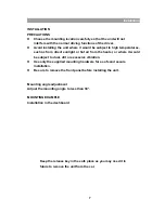
INSTALLATION 
PRECAUTIONS 

z


Choose the mounting location carefully so that the unit will not 
interfere with the normal driving functions of the driver. 

z


Avoid installing the unit where it would be subject to high temperatures, 
such as from direct sunlight or hot air from the heater, or where it would 
be subject to dust, dirt or excessive vibration. 

z


Use only the supplied mounting hardware for a safe and secure 

    installation. 

z


Be sure to remove the front panel before installing the unit. 


Mounting angle adjustment 
Adjust the mounting angle to less than 30*. 
 
MOUNTING EXAMPLE 
Installation in the dashboard 


Keep the release key in the safe place as you may need it in   

future to remove the unit from the car. 


Summary of Contents for M2150

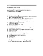
Page 1: ...Model M2150 Instruction Manual Car Stereo Compact Disc MP3 CD RW CD R CD SD MMC USB Media Player with PLL FM Stereo Radio Radio Data System RDS with PTY Detachable Front Panel System ...

Page 2: ... lock loop P L L Circuitry z Programmable 18 preset memory tuning 6 each for FM1 FM2 FM3 z EQ Control Flat POP Classic Rock z Encoder Volume Control z Loudness control Manual Auto Seek up and down tuning control z Band selector for FM1 FM2 FM3 z Display control Frequency Station Name Program Type Clock z Clock Function in RDS z CD Repeat Function z CD and MP3 files on CD CD R CD RW player function...

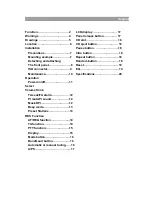
Page 3: ...button 18 Detaching and attaching Random button 18 The front panel 8 Reset 19 ISO connector 9 EQ 19 Maintenance 10 Specifications 20 Operation Power on off 11 Select Volume Knob TA seek TA alarm 12 PI mute PI sound 12 Mask DPI 12 Beep mode 13 Preset Stations 13 RDS Function AF REG function 14 TA function 14 PTY function 15 Display 15 Mode button 16 Band Loud button 16 Automatic or manual tuning 16...

Page 4: ... remove the cover No user serviceable parts inside the unit Refer all servicing to qualified personnel Invisible laser radiation when the unit is opened or interlocks defeated Avoid exposure to laser beam User of controls adjustments or procedures other than those specified herein may result in hazardous radiation exposure This unit must not be exposed to moisture or rain This unit should be posit...

Page 5: ...Drawings 5 ...
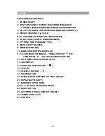
Page 6: ...ENT 7 PTY FUNCTION PROGRAM TYPE 8 DISPLAY BUTTON DISP 9 MODE BUTTON MD 10 BAND LOUD BUTTON BAND LUD 11 12 AUTOMATIC OR MANUAL TUNING FREQ UP OR FREQ DOWN CD TRACK SEARCH BUTTON 13 AUTO SEEK SEARCH TUNING A PS 14 LCD DISPLAY 15 PANEL RELEASE BUTTON 16 CD SLOT 17 CD EJECT BUTTON 18 PAUSE BUTTON 19 INTRO BUTTON PREVIEW ALL TRACKS INT 20 REPEAT BUTTON RPT 21 RANDOM BUTTON RDM 22 23 10 TRACK SEARCH DOW...

Page 7: ... sunlight or hot air from the heater or where it would be subject to dust dirt or excessive vibration z Use only the supplied mounting hardware for a safe and secure installation z Be sure to remove the front panel before installing the unit Mounting angle adjustment Adjust the mounting angle to less than 30 MOUNTING EXAMPLE Installation in the dashboard Keep the release key in the safe place as y...

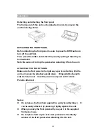
Page 8: ...t from the unit ATTACHING THE FRONT PANEL Make sure the front panel is the right way up when attaching it to the unit as it cannot be attached upside down Bring side B of panel to side A of main unit Inset the panel in and push until it clicks Panel is attached Notes z Do not press the front hard against the unit when attaching it It can be easily attached by pressing it lightly against the unit z...

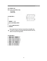
Page 9: ...N KEY 8 GROUND The connector A no 7 must be connected by car ignition key in order to avoid that car battery becomes weak when the car will be not used for long period CONNECTOR B 1 REAR RIGHT SPEAKER 2 REAR RIGHT SPEAKER 3 FRONT RIGHT SPEAKER 4 FRONT RIGHT SPEAKER 5 FRONT LEFT SPEAKER 6 FRONT LEFT SPEAKER 7 REAR LEFT SPEAKER 8 REAR LEFT SPEAKER 9 ...

Page 10: ...connection and replace the fuse If the fuse blows again after the replacement there may be an internal malfunction In this case consult your nearest repairing centre Warning Use the specified amperage fuse for each lead Use of a higher amperage fuse may cause serious damage 10 ...

Page 11: ...wn on the display Figure 1 shows how control functions are selected using the SEL button Fig 1 Selection of sound control functions 1 VOLUME 2 SELECT 3 BASS 4 TREBLE 5 BALANCE 6 FADER To increase or decrease the volume by rotating the volume knob These buttons can be used to adjust the BASS TREBLE BALANCE and FADER TA SEEK TA ALARAM 2 When press the SEL button 2 for more than 2 seconds it is activ...

Page 12: ...urrent station has no TP signal TA ALARM mode Any automatic retune mode is not activated just can be heard Beep sound PI MUTE PI SOUND When press the SEL button for more than 2 seconds it is activated as selecting mode of these function RETUNE L S When press the SEL button for more than 2 seconds it is activated as selecting mode of these function MASK DPI 2 When press the SEL button for more than...

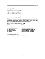
Page 13: ...c current station is stored in preset memory bank When PTY mode s selected the PTY switch is shared as follows PTY music group PTY speech group OFF MUSIC SPEECH 1 POP M ROCK M 1 NEWS AFFAIRS INFO 2 EASY M LIGHT M 2 SPORT EDUCATE DRAMA 3 CLASSICS OTHER M 3 CULTRE SCIENCE VARIED 4 JAZZ COUNTRY 4 WEATHER FINANCE CHILDREN 5 NATION M OLDIES 5 SOCIAL RELIGION PHONE IN 6 FOLK M 6 TRAVEL LEISURE DOCUMENT ...

Page 14: ...rn European countries in the near future 5 AF REG function ALTERNATIVE FREQUENCIES When press short AF REG switching mode is selected When AF REG switching mode is selected the radio checks the signal strength of the AF all the time When press long it is activated as regional mode ON OFF Regional mode ON AF switching or PI SEEK is implemented to the station which have all PI codes same as current ...

Page 15: ... in preset key When PTY is selected the radio starts to search corresponding PTY information and stops if the corresponding PTY information is detected 8 DISPLAY DISP When this button is pressed it is operated as the conversion of each display mode as follow 1 In case of receiving RDS station RADIO MODE PS CT FREQ PTY CD MP3 PLAYER MODE CDP CT PS FREQ PTY 2 In case of receiving NON RDS station RAD...

Page 16: ...ease Bass and Treble effects at low volume level LOUD appears in the display 11 12 AUTOMATIC OR MANUAL TUNING FREQ UP OR FREQ DOWN A RADIO MODE When press short these keys are operated as MANUAL tuning mode When press longer than 1 sec they are operated as Seek tuning mode B CD MP3 PLAYER MODE When press short they are operated as TRACK UP DOWN mode When press longer than 1 secretary they are oper...

Page 17: ...4 LCD DISPLAY The Liquid Crystal Display will display the current state of the unit 15 PANEL RELEASE BUTTON Press this button and the left hand part of the panel will be released CD CONTROL LOCATION OF PARTS 11 12 SKIP TRACK SEARCH BUTTON FORWARD AND REVERSE TRACK SEARCH or changing songs Press the SKIP button TUN or TUN during play to go to the desired track song TUN REVERSE TUN FORWARD Press and...

Page 18: ...again to stop intro and listen to track 20 REPEAT BUTTON RPT When this button is pressed RPT indication is displayed and play of the selected track will be continually repeated until the track Repeat mode is cancelled by pressing RPT button 20 again 21 RANDOM BUTTON RDM When this button is pressed RDM indication is displayed and each track of the disc is played in random instead of normal progress...

Page 19: ...6 10 TRACK UP SEL MENU 24 RESET Reset button 24 is placed on the housing The reset button is to be activated for the following Initial installation of the unit when all Wiring is completed All the function button do not operate Error symbol is on the display 25 ELECTRONIC EQUALISER EQ After pressing the EQ button you access control of the following menu FLAT CLASSIC POP M ROCK M DSP OFF Using thes...

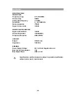
Page 20: ...se radio 60dB CD MP3 PLAYER SECTION Signal to Noise Ratio 60dB Channel Separation 50dB 1KHz Frequency Response 20Hz 20KHz LINE OUT Output 350mV max Impedance 10K Ohm GENERAL Power Supply Voltage DC 13 2 Volts Negative Ground Max Current Consumption 15A Max Output Power 25W x 4 CH Specifications and the design are subject to possible modification without notice due to improvement 20 ...

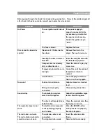
Page 21: ...ature inside the car is too high Cool off or until the ambient temperature return to normal Disc cannot be loaded or ejected Condensation Leave the player off for an hour or so then try again Volume is in minimum Adjust volume to a desired level No sound Wiring is not properly connected Check wiring connection The installation angle is more than 30 degrees Adjust the installation angle to less tha...

Reviews: