background image

PERIODIC MAINTENANCE AND MINOR REPAIR

6-38

6

a jack either under each side of the
frame in front of the rear wheel or under
each side of the swingarm.

EAU24360

Front wheel 

EAU24611

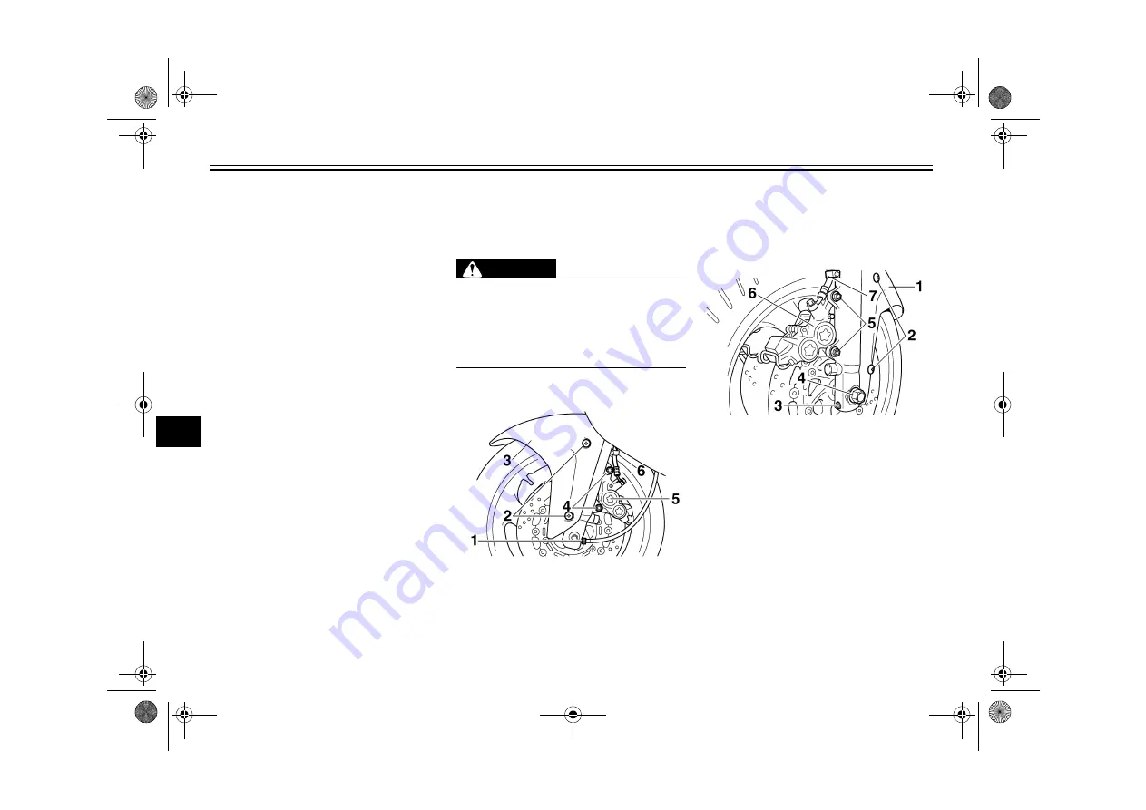
To remove the front wheel

WARNING

EWA10820

It is advisable to have a Yamaha
dealer service the wheel.

Securely support the motor-
cycle so that there is no danger
of it falling over.

1. Disconnect the speedometer ca-

ble from the front wheel.

2. Remove the front fender by remov-

ing the screws.

3. Loosen the front wheel axle pinch

bolt, then the wheel axle and the
brake caliper bolts.

4. Lift the front wheel off the ground

according to the procedure on
page 6-37.

5. Remove the brake hose holders

on each side by removing the bolt
and nut.

1. Speedometer cable

2. Screw

3. Front fender
4. Bolt

5. Brake caliper

6. Brake hose holder

1. Front fender
2. Screw

3. Front wheel axle pinch bolt

4. Wheel axle
5. Bolt

6. Brake caliper

7. Brake hose holder

5AH17.book  Page 38  Tuesday, April 8, 2003  11:35 AM

Summary of Contents for YZF600RS

Page 1: ...PRINTED IN JAPAN 2003 04 0 7 1 CR E PRINTED ON RECYCLED PAPER YAMAHA MOTOR CO LTD 5AH 28199 17 LIT 11626 17 16 YZF600RS OWNER S MANUAL ...

Page 2: ...EAU10041 5AH17 book Page 1 Tuesday April 8 2003 11 35 AM ...

Page 3: ...rcycle If you have any questions concerning the operation or maintenance of your motorcycle please consult a Yamaha dealer The design and manufacture of this Yamaha motorcycle fully comply with the emissions standards for clean air applicable at the date of manufacture Yamaha has met these standards without reducing the performance or economy of operation of the motorcycle To maintain these high s...

Page 4: ...KLET CAREFULLY AND COMPLETELY BEFORE OPERATING THIS MOTORCYCLE DO NOT ATTEMPT TO OPERATE THIS MOTOR CYCLE UNTIL YOU HAVE ATTAINED ADEQUATE KNOWLEDGE OF ITS CONTROLS AND OPERATING FEATURES AND UNTIL YOU HAVE BEEN TRAINED IN SAFE AND PROPER RIDING TECHNIQUES REGULAR INSPECTIONS AND CAREFUL MAINTENANCE ALONG WITH GOOD RIDING SKILLS WILL ENSURE THAT YOU SAFELY ENJOY THE CAPABILITIES AND THE RELIABILIT...

Page 5: ...oration U S A 1st edition March 2003 All rights reserved Any reprinting or unauthorized use without the written permission of Yamaha Motor Corporation U S A is expressly prohibited Printed in Japan P N LIT 11626 17 16 AFFIX DEALER LABEL HERE 5AH17 book Page 2 Tuesday April 8 2003 11 35 AM ...

Page 6: ... 6 1 Owner s tool kit 6 1 Periodic maintenance chart for the emission control system 6 3 General maintenance and lubrication chart 6 4 Removing and installing cowlings 6 8 Checking the spark plugs 6 10 Engine oil and oil filter cartridge 6 11 Coolant 6 14 Cleaning the air filter element 6 17 Checking the air vent hose 6 19 Air intake duct 6 19 Adjusting the carburetors 6 20 Adjusting the throttle ...

Page 7: ...the motorcycle 6 37 Front wheel 6 38 Rear wheel 6 40 Troubleshooting 6 42 Troubleshooting charts 6 43 MOTORCYCLE CARE AND STORAGE 7 1 Care 7 1 Storage 7 3 SPECIFICATIONS 8 1 CONSUMER INFORMATION 9 1 Identification numbers 9 1 Reporting safety defects 9 3 Motorcycle noise regulation 9 4 Maintenance record 9 5 YAMAHA MOTOR CORPORATION U S A STREET AND ENDURO MOTORCYCLE LIMITED WARRANTY 9 7 YAMAHA EX...

Page 8: ...ents have been caused by an automobile driver who did not see the motorcycle Making yourself conspicuous appears to be very effective in reducing the chance of this type of accident Therefore Wear a brightly colored jacket Use extra caution when you are approaching and passing through intersections since in tersections are the most likely places for motorcycle accidents to occur Ride where other m...

Page 9: ...shield or goggles Wind in your unprotected eyes could contribute to an impairment of vision that could delay seeing a hazard The use of a jacket heavy boots trousers gloves etc is effective in preventing or reducing abrasions or lacerations Never wear loose fitting clothes otherwise they could catch on the control levers footrests or wheels and cause injury or an accident Never touch the engine or...

Page 10: ...d under Load ing when mounting accessories Never install accessories or carry cargo that would impair the perfor mance of your motorcycle Care fully inspect the accessory before using it to make sure that it does not in any way reduce ground clearance or cornering clearance limit suspension travel steering travel or control operation or ob scure lights or reflectors Accessories fitted to the handl...

Page 11: ...e the following The engine and exhaust system may be hot therefore park the motorcycle in a place where pe destrians or children are not like ly to touch these hot areas Do not park the motorcycle on a slope or soft ground otherwise it may fall over Do not park the motorcycle near a flammable source e g a ker osene heater or near an open flame otherwise it could catch fire When transporting the mo...

Page 12: ...SAFETY INFORMATION 1 5 1 EAU10381 Location of important labels Please read the following important labels carefully before operating this vehicle 5AH17 book Page 5 Tuesday April 8 2003 11 35 AM ...

Page 13: ...TY INFORMATION 1 6 1 CAUTION Cleaning with alkaline or acid cleaner gasoline or solvent will damage windshield Use neutral detergent 5JW 2835Y 00 1 2 3 4 5 6 5AH17 book Page 6 Tuesday April 8 2003 11 35 AM ...

Page 14: ...sting ring page 3 12 4 Shock absorber assembly rebound damping force adjusting knob page 3 12 5 Shock absorber assembly compression damping force adjusting screw page 3 12 6 Storage compartment page 3 10 7 Helmet holder page 3 9 8 Grab bar 9 Shift pedal page 3 6 10 Radiator page 6 14 5AH17 book Page 1 Tuesday April 8 2003 11 35 AM ...

Page 15: ...nt fork spring preload adjusting bolt page 3 10 5 Front fork rebound damping force adjusting screw page 3 10 6 Radiator cap page 6 14 7 Front fork compression damping force adjusting screw page 3 10 8 Engine oil level check window page 6 11 9 Brake pedal page 3 6 10 Engine oil filler cap page 6 11 5AH17 book Page 2 Tuesday April 8 2003 11 35 AM ...

Page 16: ...es page 3 4 3 Starter choke lever page 3 8 4 Speedometer unit page 3 3 5 Tachometer page 3 3 6 Coolant temperature gauge page 3 4 7 Right handlebar switches page 3 4 8 Brake lever page 3 6 9 Throttle grip page 6 20 10 Main switch steering lock page 3 1 5AH17 book Page 3 Tuesday April 8 2003 11 35 AM ...

Page 17: ...0 LOCK The steering is locked and all electrical systems are off The key can be re moved To lock the steering 1 Turn the handlebars all the way to the left 2 Push the key in from the OFF po sition and then turn it to LOCK while still pushing it 3 Remove the key To unlock the steering Push the key in and then turn it to OFF while still pushing it WARNING EWA10060 Never turn the key to OFF or LOCK w...

Page 18: ...h have a Yamaha dealer check the electri cal circuit NOTE Even if the oil level is sufficient the warning light may flicker when riding on a slope or during sudden acceleration or deceleration but this is not a mal function EAU11320 Fuel level warning light This warning light comes on when the fuel level drops below approximately 3 1 L 0 82 us gal 0 68 imp gal When this occurs refuel as soon as po...

Page 19: ...zone Red zone 13200 r min and above EAU11981 Self diagnosis device This model is equipped with a self diag nosis device for the following electrical circuits throttle position sensor fuel level warning light If any of those circuits are defective the tachometer will repeatedly display the following error code Use the table below to identify the faulty electrical circuit If the tachometer displays ...

Page 20: ...rature of the coolant The coolant temperature varies with chang es in the weather and engine load If the needle reaches or enters the red zone stop the vehicle and let the en gine cool See page 6 43 CAUTION ECA10020 Do not operate the engine if it is overheated EAU12341 Handlebar switches Left Right 1 Coolant temperature gauge 2 Coolant temperature gauge red zone 1 Dimmer switch 2 Turn signal swit...

Page 21: ...this switch to to stop the engine in case of an emergen cy such as when the vehicle overturns or when the throttle cable is stuck EAU12710 Start switch Push this switch to crank the engine with the starter CAUTION ECA10050 See page 5 1 for starting instruc tions prior to starting the engine EAU12820 Clutch lever The clutch lever is located at the left handlebar grip To disengage the clutch pull th...

Page 22: ...equipped with a po sition adjusting dial To adjust the dis tance between the brake lever and the handlebar grip turn the adjusting dial while holding the lever pushed away from the handlebar grip Make sure that the appropriate setting on the adjusting dial is aligned with the arrow mark on the brake lever EAU12941 Brake pedal The brake pedal is on the right side of the motorcycle To apply the rear...

Page 23: ...ck cover NOTE The fuel tank cap cannot be closed un less the key is in the lock In addition the key cannot be removed if the cap is not properly closed and locked WARNING EWA11090 Make sure that the fuel tank cap is properly closed before riding EAU13210 Fuel Make sure that there is sufficient fuel in the tank Fill the fuel tank to the bottom of the filler tube as shown WARNING EWA10880 Do not ove...

Page 24: ... containing ethanol and that contain ing methanol Gasohol containing ethanol can be used if the ethanol con tent does not exceed 10 Gasohol containing methanol is not recom mended by Yamaha because it can cause damage to the fuel system or ve hicle performance problems EAU13610 Starter choke lever Starting a cold engine requires a richer air fuel mixture which is supplied by the starter choke Move...

Page 25: ...the key NOTE Make sure that the seat is properly se cured before riding EAU14290 Helmet holder To open the helmet holder insert the key into the lock and then turn the key as shown To lock the helmet holder turn the key to the original position and then re move it WARNING EWA10160 Never ride with a helmet attached to the helmet holder since the helmet may hit objects causing loss of con trol and p...

Page 26: ...hing the vehicle be careful not to let any water enter the storage compartment EAU14741 Adjusting the front fork This front fork is equipped with spring preload adjusting bolts rebound damp ing force adjusting screws and com pression damping force adjusting screws WARNING EWA10180 Always adjust both fork legs equal ly otherwise poor handling and loss of stability may result Spring preload To incre...

Page 27: ...sion damping turn the adjusting screw on each fork leg in direction a To de crease the compression damping force and thereby soften the compression damping turn the adjusting screw on each fork leg in direction b 1 Current setting 2 Front fork cap bolt Spring preload setting Minimum soft 8 Standard 5 Maximum hard 1 1 Rebound damping force adjusting screw Rebound damping setting Minimum soft 10 cli...

Page 28: ...th a spring preload adjust ing ring a rebound damping force ad justing knob and a compression damping force adjusting screw CAUTION ECA11220 Never attempt to turn the spring pre load and rebound damping force ad justing mechanisms beyond the maximum or minimum settings Spring preload To increase the spring preload and thereby harden the suspension turn the adjusting ring in direction a To de creas...

Page 29: ... decrease the setting by turning the ad justing screw To soften the compres sion damping increase the setting by turning the adjusting screw Make sure that the position indicator is aligned with the appropriate setting WARNING EWA10220 This shock absorber contains highly pressurized nitrogen gas For prop er handling read and understand the following information before handling the shock absorber T...

Page 30: ...le holding the vehicle upright NOTE The built in sidestand switch is part of the ignition circuit cut off system which cuts the ignition in certain situations See further down for an explanation of the ignition circuit cut off system WARNING EWA10240 The vehicle must not be ridden with the sidestand down or if the side stand cannot be properly moved up or does not stay up otherwise the sidestand c...

Page 31: ...s in gear and the side stand is up but the clutch lever is not pulled It prevents starting when the trans mission is in gear and the clutch le ver is pulled but the sidestand is still down It cuts the running engine when the transmission is in gear and the sid estand is moved down Periodically check the operation of the ignition circuit cut off system according to the following procedure WARNING E...

Page 32: ...ter the engine has stalled 10 Move the sidestand up 11 Keep the clutch lever pulled 12 Push the start switch Does the engine start The system is OK The motorcycle can be ridden This check is most reliable if performed with a warmed up engine The neutral switch may be defective The motorcycle should not be ridden until checked by a Yamaha dealer The sidestand switch may be defective The motorcycle ...

Page 33: ...sequences Therefore it is very important in addition to a thorough visual inspec tion to check the following points before each ride NOTE Pre operation checks should be made each time the vehicle is used Such an inspection can be accomplished in a very short time and the added safety it assures is more than worth the time involved WARNING EWA11150 If any item in the Pre operation check list is not...

Page 34: ...ft or spongy have Yamaha dealer bleed hydraulic system Check brake pads for wear Replace if necessary Check fluid level in reservoir If necessary add recommended brake fluid to specified level Check hydraulic system for leakage 6 26 6 26 Rear brake Check operation If soft or spongy have Yamaha dealer bleed hydraulic system Check brake pads for wear Replace if necessary Check fluid level in reservo...

Page 35: ...ls Make sure that operation is smooth Lubricate pedal pivoting points if necessary 6 30 Brake and clutch levers Make sure that operation is smooth Lubricate lever pivoting points if necessary 6 31 Sidestand Make sure that operation is smooth Lubricate pivot if necessary 6 31 Chassis fasteners Make sure that all nuts bolts and screws are properly tightened Tighten if necessary Instruments lights si...

Page 36: ... pulled and the sid estand up WARNING EWA10290 Before starting the engine check the function of the igni tion circuit cut off system ac cording to the procedure described on page 3 15 Never ride with the sidestand down 1 Turn the key to ON and make sure that the engine stop switch is set to CAUTION ECA10220 If the fuel level warning light comes on check the fuel level and if nec essary refuel as s...

Page 37: ...ushing the start switch or if it does not go off af ter starting with sufficient fuel have a Yamaha dealer check the electrical circuit 5 After starting the engine move the starter choke back halfway CAUTION ECA11130 For maximum engine life always warm the engine up before starting off Never accelerate hard when the engine is cold 6 When the engine is warm turn the starter choke off NOTE The engin...

Page 38: ...Even with the transmission in the neutral position do not coast for long periods of time with the engine off and do not tow the motorcycle for long dis tances The transmission is properly lubricated only when the engine is running Inade quate lubrication may damage the transmission Always use the clutch while changing gears to avoid damag ing the engine transmission and drive train which are not d...

Page 39: ... EAU16740 Recommended shift points The recommended shift points during acceleration and deceleration are shown in the table below EAU16841 Engine break in There is never a more important period in the life of your engine than the period between 0 and 1600 km 1000 mi For this reason you should read the follow ing material carefully Since the engine is brand new do not put an excessive load on it fo...

Page 40: ...ometer red zone If any engine trouble should oc cur during the engine break in period immediately have a Yamaha dealer check the vehi cle EAU17200 Parking When parking stop the engine and then remove the key from the main switch WARNING EWA10310 Since the engine and exhaust system can become very hot park in a place where pedestri ans or children are not likely to touch them Do not park on a slope...

Page 41: ...EMISSIONS CONTROL THESE CONTROLS NOT ONLY FUNCTION TO ENSURE CLEANER AIR BUT ARE ALSO VITAL TO PROPER EN GINE OPERATION AND MAXIMUM PERFORMANCE IN THE FOLLOW ING PERIODIC MAINTENANCE CHARTS THE SERVICES RELATED TO EMISSIONS CONTROL ARE GROUPED SEPARATELY THESE SERVICES REQUIRE SPECIALIZED DATA KNOWLEDGE AND EQUIP MENT YAMAHA DEALERS ARE TRAINED AND EQUIPPED TO PER FORM THESE PARTICULAR SER VICES E...

Page 42: ...WARNING EWA10340 Modifications not approved by Yamaha may cause loss of perfor mance excessive emissions and render the vehicle unsafe for use Consult a Yamaha dealer before at tempting any changes 5AH17 book Page 2 Tuesday April 8 2003 11 35 AM ...

Page 43: ...uel line Check fuel hose for cracks or damage Replace if necessary 2 Fuel filter Replace Replace 3 Spark plugs Check condition Adjust gap and clean Replace every 8000 mi 13000 km or 12 months Replace Replace 4 Valve clearance Check and adjust valve clearance when engine is cold Every 26600 mi 42000 km 5 Crankcase breather system Check breather hose for cracks or damage Replace if necessary 6 Carbu...

Page 44: ... operation Adjust or replace cable 3 Front brake Check operation fluid level and for fluid leakage See NOTE Replace brake pads if necessary 4 Rear brake Check operation fluid level and for fluid leakage See NOTE Replace brake pads if necessary 5 Brake hoses Check for cracks or damage Replace See NOTE Every 4 years 6 Wheels Check runout and for damage Replace if necessary 7 Tires Check tread depth ...

Page 45: ...ths Repack 12 Chassis fasteners Check all chassis fitting and fas teners Correct if necessary 13 Brake and clutch le ver pivot shafts Apply lithium soap based grease all purpose grease lightly 14 Brake and shift ped al pivot shafts Apply lithium soap based grease all purpose grease lightly 15 Sidestand pivot Check operation Apply lithium soap based grease all purpose grease lightly 16 Sidestand sw...

Page 46: ...e 22 Cooling system Check hoses for cracks or dam age Replace if necessary Change with ethylene glycol anti freeze coolant every 24 months Change 23 Control and meter cables Apply Yamaha chain and cable lube or engine oil 10W 30 thor oughly 24 Throttle grip hous ing and cable Check operation and free play Adjust the throttle cable free play if necessary Lubricate the throttle grip housing and cabl...

Page 47: ...nusually wet or dusty areas Hydraulic brake service After disassembling the brake master cylinders and calipers always change the fluid Regularly check the brake fluid levels and fill the reservoirs as required Every two years replace the internal components of the brake master cylinders and calipers and change the brake fluid Replace the brake hoses every four years and if cracked or damaged 5AH1...

Page 48: ...this section each time a cowl ing needs to be removed and installed EAU18911 Cowlings A and C To remove one of the cowlings 1 Remove the bolts 2 Disconnect the turn signal light lead connectors and for the left side cowling also the auxiliary light lead coupler and then take the cowling off 1 Cowling A 2 Cowling B 1 Cowling C 2 Cowling D 1 Bolt 1 Bolt 1 Bolt 5AH17 book Page 8 Tuesday April 8 2003 ...

Page 49: ... To install the cowling 1 Place the cowling in the original position and then install the screws 2 Install the seat EAU19020 Cowling D To remove the cowling 1 Remove the seat and cowling B See pages 3 9 and 6 8 2 Remove the grab bar by removing the bolts 3 Remove the screw and then pull the cowling off as shown To install the cowling 1 Place the cowling in the original position and then install th...

Page 50: ... that the porcelain insulator around the center electrode on each spark plug is a medium to light tan the ideal color when the vehicle is ridden normally 2 Check that all spark plugs installed in the engine have the same color NOTE If any spark plug shows a distinctly dif ferent color the engine could be defec tive Do not attempt to diagnose such problems yourself Instead have a Yamaha dealer chec...

Page 51: ...ked before each ride In addition the oil must be changed and the oil filter car tridge replaced at the intervals speci fied in the periodic maintenance and lubrication chart To check the engine oil level 1 Place the vehicle on a level sur face and hold it in an upright posi tion NOTE Make sure that the vehicle is positioned straight up when checking the oil level A slight tilt to the side can resu...

Page 52: ... 2 Start the engine warm it up for several minutes and then turn it off 3 Place an oil pan under the engine to collect the used oil 4 Remove the engine oil filler cap and drain bolt to drain the oil from the crankcase NOTE Skip steps 5 7 if the oil filter cartridge is not being replaced 5 Remove the oil filter cartridge with an oil filter wrench 1 Engine oil level check window 2 Maximum level mark...

Page 53: ... do not mix any chemical additives Do not use oils with a diesel speci fication of CD or oils of a high er quality than specified In addition do not use oils labeled ENERGY CONSERVING II or higher Make sure that no foreign mate rial enters the crankcase 10 Start the engine and then let it idle for several minutes while checking it for oil leakage If oil is leaking im mediately turn the engine off ...

Page 54: ...NOTE The coolant level must be checked on a cold engine since the level varies with engine temperature Make sure that the vehicle is posi tioned straight up when checking the coolant level A slight tilt to the side can result in a false reading 2 Remove the seat See page 3 9 3 Check the coolant level in the cool ant reservoir NOTE The coolant should be between the minimum and maximum level marks 4...

Page 55: ...adiator cap when the engine is hot NOTE The radiator fan is automatically switched on or off according to the coolant temperature in the radia tor If the engine overheats see page 6 43 for further instructions EAU20411 To change the coolant 1 Place the vehicle on a level sur face and let the engine cool if nec essary 2 Remove the seat See page 3 9 3 Remove cowlings A C and D See page 6 8 4 Remove ...

Page 56: ...ghly flush the cool ing system with clean tap water 13 Install the coolant reservoir by in stalling the screws 14 Install the water pump drain bolt and cylinder drain bolts and then tighten them to the specified torques 15 Pour the specified amount of rec ommended coolant into the reser voir to the maximum level mark and then install the coolant reser voir cap 16 Pour the recommended coolant into ...

Page 57: ...22 Place the fuel tank in the original position and then install the bolts 23 Install the cowlings 24 Install the seat EAU20931 Cleaning the air filter element The air filter element should be cleaned at the intervals specified in the periodic maintenance and lubrication chart Clean the air filter element more fre quently if you are riding in unusually wet or dusty areas 1 Remove the seat See page...

Page 58: ...ponge material should be wet but not dripping 8 Insert the air filter element into the air filter case CAUTION ECA10480 Make sure that the air filter ele ment is properly seated in the air filter case The engine should never be op erated without the air filter ele ment installed otherwise the piston s and or cylinder s may become excessively worn 9 Install the air filter case cover by in stalling ...

Page 59: ...and not pinched 11 Install the seat EAU21200 Checking the air vent hose Periodically check the air vent hose for dust or water that may be deposited in the hose If dust or water is found re move the air vent hose thoroughly clean it and then install it CAUTION ECA10540 Do not operate the motorcycle with the air vent hose removed EAU21210 Air intake duct Check that the screen of the intake duct is ...

Page 60: ...e free play The throttle cable free play should mea sure 3 0 7 0 mm 0 12 0 28 in at the throttle grip Periodically check the throttle cable free play and if neces sary have a Yamaha dealer adjust it EAU21400 Adjusting the valve clearance The valve clearance changes with use resulting in improper air fuel mixture and or engine noise To prevent this from occurring the valve clearance must be adjuste...

Page 61: ...t Securely pack your heavi est items close to the center of the vehicle and distribute the weight evenly from side to side Properly adjust the suspension for your load and check the condition and pres sure of your tires NEVER OVER LOAD YOUR VEHICLE Make sure that the total weight of the cargo rid er passenger and accessories cowling saddlebags etc if ap proved for this model does not ex ceed the m...

Page 62: ... EWA10480 The front and rear tires should be of the same make and de sign otherwise the handling characteristics of the motor cycle cannot be guaranteed After extensive tests only the tires listed below have been ap proved for this model by Yamaha Motor Co Ltd Always make sure that the valve caps are securely installed to prevent air pressure leakage Use only the tire valves and valve cores listed...

Page 63: ...he wheel A deformed or cracked wheel must be replaced The wheel should be balanced whenever either the tire or wheel has been changed or replaced An unbalanced wheel can result in poor performance adverse han dling characteristics and a short ened tire life Ride at moderate speeds after changing a tire since the tire sur face must first be broken in for it to develop its optimal characteris tics E...

Page 64: ...s follows 1 Loosen the locknut at the clutch le ver 2 To increase the clutch lever free play turn the adjusting bolt in di rection a To decrease the clutch lever free play turn the adjusting bolt in direction b 3 Tighten the locknut NOTE If the specified free play cannot be ob tained as described above or if the clutch does not operate correctly have a Yamaha dealer check the internal clutch mecha...

Page 65: ...raulic system will diminish the braking performance which may result in loss of control and an acci dent EAU22270 Adjusting the rear brake light switch The rear brake light switch which is ac tivated by the brake pedal is properly adjusted when the brake light comes on just before braking takes effect If necessary adjust the brake light switch as follows Turn the adjusting nut while holding the re...

Page 66: ...mble the brake To check the brake pad wear check the position of the wear indicator while applying the brake If a brake pad has worn to the point that the wear indi cator almost touches the brake disc have a Yamaha dealer replace the brake pads as a set EAU22580 Checking the brake fluid level Front brake Rear brake Insufficient brake fluid may allow air to enter the brake system possibly caus ing ...

Page 67: ...t water does not en ter the brake fluid reservoir when refilling Water will significantly lower the boiling point of the fluid and may result in vapor lock Brake fluid may deteriorate paint ed surfaces or plastic parts Al ways clean up spilled fluid immediately As the brake pads wear it is nor mal for the brake fluid level to grad ually go down However if the brake fluid level goes down sud denly ...

Page 68: ...drive chain slack 1 Loosen the axle nut then loosen the locknut at each end of the swingarm 2 To tighten the drive chain turn the adjusting nut at each end of the swingarm in direction a To loos en the drive chain turn the adjust ing nut at each end of the swingarm in direction b and then push the rear wheel forward NOTE Using the alignment marks on each side of the swingarm make sure that both ad...

Page 69: ...n must be lubricated after washing the motorcycle or riding in the rain 1 Clean the drive chain with kero sene and a small soft brush CAUTION ECA11120 To prevent damaging the O rings do not clean the drive chain with steam cleaners high pressure washers or inappropriate solvents 2 Wipe the drive chain dry 3 Thoroughly lubricate the drive chain with a special O ring chain lubricant CAUTION ECA11110...

Page 70: ... bles as soon as possible to prevent unsafe conditions EAU23110 Checking and lubricating the throttle grip and cable The operation of the throttle grip should be checked before each ride In addi tion the cable should be lubricated or replaced at the intervals specified in the periodic maintenance chart EAU23131 Checking and lubricating the brake and shift pedals The operation of the brake and shif...

Page 71: ...etal to metal contact surfaces should be lubricated if necessary WARNING EWA10730 If the sidestand does not move up and down smoothly have a Yamaha dealer check or repair it EAU23250 Lubricating the rear suspension The pivoting points of the rear suspen sion must be lubricated at the intervals specified in the periodic maintenance and lubrication chart Recommended lubricant Lithium soap based grea...

Page 72: ... to check if the front fork compresses and rebounds smoothly CAUTION ECA10590 If any damage is found or the front fork does not operate smoothly have a Yamaha dealer check or re pair it EAU23280 Checking the steering Worn or loose steering bearings may cause danger Therefore the operation of the steering must be checked as fol lows at the intervals specified in the pe riodic maintenance and lubric...

Page 73: ...aintenance There is no need to check the electrolyte or to add distilled water CAUTION ECA10620 Never attempt to remove the battery cell seals as this would permanent ly damage the battery WARNING EWA10760 Electrolyte is poisonous and dangerous since it contains sul furic acid which causes severe burns Avoid any contact with skin eyes or clothing and al ways shield your eyes when working near batt...

Page 74: ...he battery fully charge it and then place it in a cool dry place 2 If the battery will be stored for more than two months check it at least once a month and fully charge it if necessary 3 Fully charge the battery before in stallation 4 After installation make sure that the battery leads are properly con nected to the battery terminals CAUTION ECA10630 Always keep the battery charged Storing a disc...

Page 75: ... possibly a fire 3 Turn the key to ON and turn on the electrical circuit in question to check if the device operates 4 If the fuse immediately blows again have a Yamaha dealer check the electrical system EAU23740 Replacing the headlight bulb This model is equipped with a quartz bulb headlight If the headlight bulb burns out replace it as follows 1 Disconnect the headlight coupler and then remove t...

Page 76: ...ee from oil otherwise the transpar ency of the glass the luminosity of the bulb and the bulb life will be adversely affected Thor oughly clean off any dirt and fin gerprints on the headlight bulb using a cloth moistened with al cohol or thinner Headlight lens Do not affix any type of tinted film or stickers to the headlight lens Do not use a headlight bulb of a wattage higher than specified 4 Inst...

Page 77: ... CAUTION ECA11190 Do not overtighten the screw other wise the lens may break EAU24350 Supporting the motorcycle Since this model is not equipped with a centerstand follow these precautions when removing the front and rear wheel or performing other maintenance requiring the motorcycle to stand up right Check that the motorcycle is in a stable and level position before starting any maintenance A str...

Page 78: ...e speedometer ca ble from the front wheel 2 Remove the front fender by remov ing the screws 3 Loosen the front wheel axle pinch bolt then the wheel axle and the brake caliper bolts 4 Lift the front wheel off the ground according to the procedure on page 6 37 5 Remove the brake hose holders on each side by removing the bolt and nut 1 Speedometer cable 2 Screw 3 Front fender 4 Bolt 5 Brake caliper 6...

Page 79: ...front wheel so that it is on the ground 5 Install the brake calipers by install ing the bolts NOTE Make sure that there is enough space between the brake pads before install ing the brake calipers onto the brake discs 6 Install the brake hose holders by installing the bolts and nuts 7 Tighten the wheel axle then the front wheel axle pinch bolt and the brake caliper bolts to the specified torques 8...

Page 80: ...ve the brake caliper by remov ing the bolts 5 Disconnect the brake torque rod from the brake caliper bracket by removing the nut and the bolt 6 Loosen the locknut and the drive chain slack adjusting nut on both sides of the swingarm 7 Push the wheel forward and then remove the drive chain from the rear sprocket NOTE The drive chain does not need to be disassembled in order to remove and install th...

Page 81: ...on the ground 4 Install the brake caliper by install ing the bolts and then connect the brake torque rod to the brake cali per bracket by installing the bolt and nut NOTE Make sure that there is enough space between the brake pads before install ing the brake caliper onto the brake disc 5 Tighten the axle nut the brake cal iper bolts and the brake torque rod nut to the specified torques 6 Install ...

Page 82: ...g troubleshooting charts represent quick and easy procedures for checking these vital systems your self However should your motorcycle require any repair take it to a Yamaha dealer whose skilled technicians have the necessary tools experience and know how to service the motorcycle properly Use only genuine Yamaha replace ment parts Imitation parts may look like Yamaha parts but they are often infe...

Page 83: ...compression Check the ignition Have a Yamaha dealer check the vehicle Remove the spark plugs and check the electrodes 3 Ignition Wipe off with a dry cloth and correct the spark plug gaps or replace the spark plugs Have a Yamaha dealer check the vehicle The engine does not start Have a Yamaha dealer check the vehicle The engine does not start Check the battery Operate the electric starter 4 Battery...

Page 84: ...e hissing sound has stopped press down on the cap while turning it counterclockwise and then remove the cap NOTE If coolant is not available tap water can be temporarily used instead provided that it is changed to the recommended coolant as soon as possible Wait until the engine has cooled Check the coolant level in the reservoir and radiator The coolant level is OK The coolant level is low Check ...

Page 85: ...e dirt do not leave the cleaner on the af fected area any longer than in structed Also thoroughly rinse the area off with water immedi ately dry it and then apply a cor rosion protection spray Improper cleaning can damage windshields cowlings panels and other plastic parts Use only a soft clean cloth or sponge with mild detergent and water to clean plastic Do not use any harsh chemical products on...

Page 86: ...sion After cleaning 1 Dry the motorcycle with a chamois or an absorbing cloth 2 Immediately dry the drive chain and lubricate it to prevent it from rusting 3 Use a chrome polish to shine chrome aluminum and stainless steel parts including the exhaust system Even the thermally in duced discoloring of stainless steel exhaust systems can be re moved through polishing 4 To prevent corrosion it is reco...

Page 87: ...is chapter 2 For motorcycles equipped with a fuel cock that has an OFF posi tion Turn the fuel cock lever to OFF 3 Drain the carburetor float chamber by loosening the drain bolt this will prevent fuel deposits from building up Pour the drained fuel into the fuel tank 4 Fill up the fuel tank and add fuel stabilizer if available to prevent the fuel tank from rusting and the fuel from deteriorating 5...

Page 88: ...wheels are off the ground Alterna tively turn the wheels a little every month in order to prevent the tires from becoming degraded in one spot 8 Cover the muffler outlet with a plastic bag to prevent moisture from entering it 9 Remove the battery and fully charge it Store it in a cool dry place and charge it once a month Do not store the battery in an ex cessively cold or warm place less than 0 C ...

Page 89: ...ent 2 90 L 3 07 us qt 2 55 Imp qt Cooling system Coolant reservoir capacity up to the maximum level mark 0 30 L 0 32 us qt 0 26 Imp qt Radiator capacity including all routes 1 95 L 2 06 us qt 1 72 Imp qt Air filter Air filter element Wet element Fuel Recommended fuel Unleaded gasoline only Fuel tank capacity 19 0 L 5 02 us gal 4 18 imp gal Fuel reserve amount 3 1 L 0 82 us gal 0 68 imp gal Carbure...

Page 90: ...del METZELER MEZ1 Loading Maximum load 182 0 kg 401 lb Total weight of rider passenger cargo and accessories Tire air pressure measured on cold tires Loading condition 0 0 90 0 kg 0 198 lb Front 225 kPa 33 psi 2 25 kgf cm Rear 250 kPa 36 psi 2 50 kgf cm Loading condition 90 0 182 0 kg 198 401 lb Front 250 kPa 36 psi 2 50 kgf cm Rear 290 kPa 42 psi 2 90 kgf cm High speed riding Front 250 kPa 36 psi...

Page 91: ...acity 12 V 10 0 Ah Headlight Bulb type Halogen bulb Bulb voltage wattage x quantity Headlight 12 V 60 0 W 55 0 W 1 Tail brake light 12 V 8 0 W 27 0 W 1 Front turn signal position light 12 V 27 0 W 8 0 W 2 Rear turn signal light 12 V 27 0 W 2 Meter lighting 12 V 1 7 W 4 Neutral indicator light 12 V 3 4 W 1 High beam indicator light 12 V 3 4 W 1 Oil level warning light 12 V 3 4 W 1 Turn signal indic...

Page 92: ...entification number The key identification number is stamped into the key tag Record this number in the space provided and use it for reference when ordering a new key EAU26400 Vehicle identification number The vehicle identification number is stamped into the steering head pipe Record this number in the space pro vided NOTE The vehicle identification number is used to identify your motorcycle and...

Page 93: ... label is affixed to the frame under the seat See page 3 9 Record the information on this label in the space provided This information will be needed when ordering spare parts from a Yamaha dealer 1 Model label 5AH17 book Page 2 Tuesday April 8 2003 11 35 AM ...

Page 94: ...estigation and if it finds that a safety defect exists in a group of vehicles it may order a recall and remedy campaign However NHTSA cannot become involved in individual problems between you your dealer or Yamaha Motor Corporation U S A To contact NHTSA you may either call the Auto Safety Hotline toll free at 1 800 424 9393 or 366 0123 in Washington D C area or write to NHTSA U S Department of Tr...

Page 95: ...hicle for the purpose of noise control prior to its sale or delivery to the ultimate purchaser or while it is in use or 2 the use of the vehicle after such device or element of design has been removed or rendered inoperative by any person AMONG THOSE ACTS PRESUMED TO CONSTITUTE TAMPERING ARE THE ACTS LISTED BELOW These acts include tampering with the following systems i e modification removal etc ...

Page 96: ...eminder that maintenance work is required It is not acceptable proof of maintenance work Maintenance interval Date of service Mileage Servicing dealer name and address Remarks 600 mi 1000 km or 1 month 4000 mi 7000 km or 6 months 8000 mi 13000 km or 12 months 12000 mi 19000 km or 18 months 16000 mi 25000 km or 24 months 20000 mi 31000 km or 30 months 24000 mi 37000 km or 36 months 28000 mi 43000 k...

Page 97: ...FORMATION 9 6 9 36000 mi 55000 km or 54 months 40000 mi 61000 km or 60 months Maintenance interval Date of service Mileage Servicing dealer name and address Remarks 5AH17 book Page 6 Tuesday April 8 2003 11 35 AM ...

Page 98: ...CONSUMER INFORMATION 9 7 9 EAU26661 YAMAHA MOTOR CORPORATION U S A STREET AND ENDURO MOTORCYCLE LIMITED WARRANTY 5AH17 book Page 7 Tuesday April 8 2003 11 35 AM ...

Page 99: ...CONSUMER INFORMATION 9 8 9 5AH17 book Page 8 Tuesday April 8 2003 11 35 AM ...

Page 100: ...ed repairs There s no deductible to pay and repairs aren t pro rated You don t have any out of pocket expenses for covered repairs In addition Travel and Recreation Interruption Protection TRIP is included at no extra cost TRIP gives you up to 150 reimbursement per occurrence for any reasonable expenses you incur because your Yamaha needs covered service replacement vehicle rental emergency towing...

Page 101: ...cked protection even after your Yamaha Limited Warranty expires A special note If visiting your dealer isn t convenient contact Yamaha with your Primary ID number your frame number We ll be happy to help you get the Y E S coverage you need Yamaha Service Marketing P O Box 6555 Cypress CA 90630 1 866 YES EXTD 1 866 937 3983 5AH17 book Page 10 Tuesday April 8 2003 11 35 AM ...

Page 102: ... High beam indicator light 3 2 Horn switch 3 5 I Identification numbers 9 1 Ignition circuit cut off system 3 15 Indicator and warning lights 3 2 K Key identification number 9 1 L Labels location of 1 5 Luggage strap holders 3 14 M Main switch steering lock 3 1 Maintenance and lubrication periodic 6 4 Maintenance emission control system 6 3 Maintenance periodic 6 1 Maintenance record 9 5 Model lab...

Page 103: ... 43 Turn signal indicator light 3 2 Turn signal light bulb replacing 6 37 Turn signal switch 3 5 V Valve clearance adjusting 6 20 Vehicle identification number 9 1 W Warranty extended 9 9 Warranty limited 9 7 Wheel bearings checking 6 33 Wheel front 6 38 Wheel rear 6 40 Wheels 6 23 5AH17 book Page 2 Tuesday April 8 2003 11 35 AM ...

Page 104: ...PRINTED IN JAPAN 2003 04 0 7 1 CR E PRINTED ON RECYCLED PAPER YAMAHA MOTOR CO LTD 5AH 28199 17 LIT 11626 17 16 YZF600RS OWNER S MANUAL ...

Reviews: