Instrument an
d
control functions
4-21
4
TIP
Use the special wrench and extension
bar in the additional tool kit to make
this adjustment.
Re
b
oun
d
d
ampin
g
force
Turn the adjusting screw in direction (a)
to increase the rebound damping for-
ce.
Turn the adjusting screw in direction (b)
to decrease the rebound damping for-
ce.
To set the rebound damping force, turn
the adjuster in direction (a) until it
stops, and then count the turns in di-
rection (b).
TIP
When turning the damping force ad-
juster in direction (b), it may turn be-
yond the stated specifications,
however such adjustments are ineffec-
tive and may damage the suspension.
WARNING
EWA10222
This shock a
b
sor
b
er assem
b
ly con-
tains hi
g
hly pressurize
d
nitro
g
en
g
as. Rea
d
an
d
un
d
erstan
d
the fol-
lowin
g
information
b
efore han
d
lin
g
the shock a
b
sor
b
er assem
b
ly.
Do not tamper with or attempt
to open the cylin
d
er assem
b
ly.
Do not su
b
ject the shock a
b
-
sor
b
er assem
b
ly to an open
flame or other hi
g
h heat source.
This may cause the unit to ex-
plo
d
e
d
ue to excessive
g
as
pressure.
Do not
d
eform or
d
ama
g
e the
cylin
d
er in any way. Cylin
d
er
d
ama
g
e will result in poor
d
ampin
g
performance.
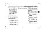
1. Extension bar
2. Special wrench
3. Spring preload adjusting ring
4. Position indicator
Sprin
g
preloa
d
settin
g
:
Minimum (soft):
1
Standard:
4
Maximum (hard):
7
7 6 5
4 3 2
1
3
3
2
1
3
(b)
(b)
(a)
(a)
(b)
(a)
2
1
4
1. Rebound damping force adjusting screw
Re
b
oun
d
d
ampin
g
settin
g
:
Minimum (soft):
2.5 turn(s) in direction (b)
Standard:
1.5 turn(s) in direction (b)
Maximum (hard):
0 turn(s) in direction (b)
1 (a)
(b)
UBATEZE0.book Page 21 Monday, December 14, 2020 1:08 PM


