background image

1
2
3
4
5
6
7
8
9

10

TUNING

ENGINE

.............................................................................................................8-1

CARBURETOR SETTING ..........................................................................8-1
ATMOSPHERIC CONDITIONS AND CARBURETOR SETTINGS ............8-1
TEST RUN..................................................................................................8-1
EFFECTS OF THE SETTING PARTS ON THE THROTTLE VALVE 

OPENING ..................................................................................................8-2

MAIN JET ADJUSTMENT ..........................................................................8-2
ADJUSTING THE POWER JET .................................................................8-2
PILOT AIR SCREW ADJUSTMENT...........................................................8-2
PILOT JET ADJUSTMENT.........................................................................8-3
JET NEEDLE ADJUSTMENT.....................................................................8-3
JET NEEDLE GROOVE POSITION ADJUSTMENT ..................................8-4
RELATIONSHIP WITH THROTTLE OPENING..........................................8-4
CARBURETOR SETTING PARTS .............................................................8-5
ROAD CONDITION AND EXAMPLES OF CARBURETOR SETTING.......8-6
EXAMPLES OF CARBURETOR SETTING DEPENDING ON 

SYMPTOM.................................................................................................8-6

CHANGE OF THE HEAT RANGE OF SPARK PLUGS..............................8-8

CHASSIS

..........................................................................................................8-9

SELECTION OF THE SECONDARY REDUCTION RATIO 

(SPROCKET).............................................................................................8-9

DRIVE AND REAR WHEEL SPROCKETS SETTING PARTS...................8-9
TIRE PRESSURE.......................................................................................8-9
FRONT FORK SETTING..........................................................................8-10
CHANGE IN AMOUNT AND CHARACTERISTICS OF FORK OIL ..........8-10
SETTING OF SPRING AFTER REPLACEMENT.....................................8-10
FRONT FORK SETTING PARTS.............................................................8-11
REAR SUSPENSION SETTING...............................................................8-11
CHOOSING SET LENGTH.......................................................................8-11
SETTING OF SPRING AFTER REPLACEMENT.....................................8-12
REAR SHOCK ABSORBER SETTING PARTS .......................................8-12
SUSPENSION SETTING (FRONT FORK)...............................................8-14
SUSPENSION SETTING (REAR SHOCK ABSORBER)..........................8-15

Summary of Contents for YZ250 2021

Page 1: ...99 10 LIT 11626 34 11 Read this manual carefully before operating this vehicle YZ250M2 YZ250XM OWNER S MANUAL YZ250 YZ250X 2021 PRINTED IN JAPAN 2020 04 0 9 1 E BF1 28199 10_cover indd 1 3 2020 03 10 13 38 50 ...

Page 2: ...riginally equipped on your vehicle providing you with the performance and durability you have come to expect Why settle for aftermarket parts that may not provide full confidence and satisfaction Genuine Yamaha Accessories Yamaha only offers accessories that meet our high standards for quality and performance Buy with confidence knowing your Genuine Yamaha Accessories will fit right and perform ri...

Page 3: ...021 by Yamaha Motor Corporation U S A First edition April 2020 All rights reserved Any reprinting or unauthorized use without the written permission of Yamaha Motor Corporation U S A is expressly prohibited P N LIT 11626 34 11 Printed in Japan ...

Page 4: ...quested not to undertake inspection adjustment disassem bly or reassembly only by reference to this manual It may lead to servicing trouble and mechanical damage WARNING EWA20270 PLEASE READ THIS MANUAL CAREFULLY AND COMPLETELY BEFORE OPERATING THIS MACHINE DO NOT ATTEMPT TO OPERATE THIS MACHINE UNTIL YOU HAVE ATTAINED A SATISFACTORY KNOWLEDGE OF ITS CONTROLS AND OPERATING FEATURES AND UNTIL YOU H...

Page 5: ...EAM20162 YAMAHA MOTOR CORPORATION U S A YZ MOTORCYCLE LIMITED WARRANTY ...

Page 6: ......

Page 7: ...GENERAL INFORMATION 1 SPECIFICATIONS 2 PERIODIC CHECKS AND ADJUSTMENTS 3 CHASSIS 4 ENGINE 5 ELECTRICAL SYSTEM 6 TROUBLESHOOTING 7 TUNING 8 EAM10003 TABLE OF CONTENTS ...

Page 8: ......

Page 9: ...REPARATION FOR REMOVAL AND DISASSEMBLY 1 8 REPLACEMENT PARTS 1 8 INSTRUMENT AND CONTROL FUNCTIONS 1 9 ENGINE STOP SWITCH 1 9 SHIFT PEDAL 1 9 KICKSTARTER LEVER 1 9 FRONT BRAKE LEVER 1 9 REAR BRAKE PEDAL 1 9 FUEL COCK for YZ250 1 9 FUEL COCK for YZ250X 1 10 STARTER KNOB CHOKE 1 10 SIDESTAND for YZ250X 1 10 STARTING AND BREAK IN 1 11 FUEL AND ENGINE MIXING OIL 1 11 STARTING A COLD ENGINE 1 11 STARTIN...

Page 10: ...MOTORCYCLE CARE AND STORAGE 1 16 CARE 1 16 STORAGE 1 17 ...

Page 11: ...re riding 2 This motorcycle is designed to carry the oper ator only No passengers 3 The failure of motorists to detect and recog nize motorcycles in traffic is the predominat ing cause of automobile motorcycle accidents Many accidents have been caused by an automobile driver who did not see the motorcycle Making yourself conspic uous appears to be very effective in reducing the chance of this type...

Page 12: ... Many companies with no connection to Yamaha manufacture parts and accessories or offer oth er modifications for Yamaha vehicles Yamaha is not in a position to test the products that these aftermarket companies produce Therefore Yamaha can neither endorse nor recommend the use of accessories not sold by Yamaha or modifications not specifically recommended by Yamaha even if sold and installed by a ...

Page 13: ...he fuel cock if equipped is in the OFF position and that there are no fuel leaks 3 Point the front wheel straight ahead on the trailer or in the truck bed and choke it in a rail to prevent movement 4 Shift the transmission in gear for models with a manual transmission 5 Secure the motorcycle with tie downs or suit able straps that are attached to solid parts of the motorcycle such as the frame or ...

Page 14: ...LOCATION OF IMPORTANT LABELS 1 4 EAM20085 LOCATION OF IMPORTANT LABELS Please read the following important labels carefully before operating this vehicle ...

Page 15: ...be different from those for the vehicle you have purchased 1 Clutch lever 2 Engine stop switch 3 Front brake lever 4 Throttle grip 5 Radiator cap 6 Fuel tank cap 7 Kickstarter lever 8 Fuel tank 9 Radiator 10 Coolant drain bolt 11 Check bolt Transmission oil level 12 Rear brake pedal 13 Valve joint 14 Fuel cock 15 Starter knob 16 Drive chain 17 Air filter 18 Shift pedal 19 Front fork ...

Page 16: ...or positive identi fication of the model you own 2 If your vehicle is stolen the authorities will need the number to search for and identify your vehicle EAM30002 VEHICLE IDENTIFICATION NUMBER The vehicle identification number 1 is stamped into the right side of the frame EAM30003 ENGINE SERIAL NUMBER The engine serial number 1 is stamped into the elevated part of the right side of the engine ...

Page 17: ...ENCH The nipple wrench 1 is used to tighten the spoke EAM30534 VALVE JOINT This valve joint 1 prevents fuel from flowing out and is installed to the fuel tank breather hose NOTICE ECA27110 In this installation make sure the arrow fac es the fuel tank and also downward EAM30535 SET PIN This set pin 1 is used to remove and install the push rod of the engine NOTICE ECA27140 Be sure to use the set pin...

Page 18: ...ot to re ceive an injury or a burn on the engine the exhaust pipe the silencer or the like 6 If coolant is left adhered to the chassis paint and plating will be damaged Therefore rinse it out with water in good time WARNING EWA18970 Coolant is potentially harmful and should be handled with special care If it enters your eyes wash it away with wa ter enough and then get medical attention If it spla...

Page 19: ...a primary kickstarter lever so the engine can be started in any gear if the clutch is disengaged In normal practices however shift to neutral be fore starting EAM30188 FRONT BRAKE LEVER The front brake lever 1 is located on the right handlebar Pull it toward the handlebar to acti vate the front brake EAM30189 REAR BRAKE PEDAL The rear brake pedal 1 is in the right of the chassis Press down on the ...

Page 20: ...serve section of the fuel tank after the main supply of the fuel has been depleted Normal riding is possible with the lever is in this position but it is recommended to add fuel as soon as possible EAM30444 STARTER KNOB CHOKE When cold the engine requires a richer air fuel mixture for starting A separate starter circuit which is controlled by the starter knob 1 sup plies this mixture Pull the star...

Page 21: ...6 To stop the engine push the engine stop switch TIP Continue pushing the engine stop switch till the engine comes to a full stop EAM30197 STARTING A WARM ENGINE Do not operate the starter knob CHOKE Open the throttle slightly and start the engine by kick ing the kickstarter forcefully with firm stroke EAM30198 BREAK IN PROCEDURES A break in is important so that rotating portion sliding surfaces a...

Page 22: ...n them Also when the following parts are replaced a break in is required Cylinder and Crankshaft A break in is re quired for about an hour Piston Piston ring Valve Camshaft and Gear A break in is required for about 30 minutes at a throttle opening of 1 2 or less Observe the condition of the engine carefully during a break in For checkpoints for a break in see MAIN TENANCE AFTER BREAK IN If any pro...

Page 23: ... nuts Check for looseness in mounted areas of parts as well as engine mounting bolts and engine brackets 2 For the chassis Check welds and mounted areas of the frame the swingarm the link the bracket and so on for looseness and cracks Wheel s Check the wheel for runout Check the spoke for looseness Brake s Check the brake disc mounting bolt for loose ness Check that the reservoir contains the spec...

Page 24: ...k to swingarm Mounting of rear shock absorber Rear shock absorber and frame Mounting of swingarm Tightening of pivot shaft Wheel s Mounting of wheel Front Tightening of wheel axle Tightening of axle holder Tightening of spoke nipple Rear Tightening of wheel axle Wheel to rear wheel sprocket Tightening of spoke nipple Brake s Front Brake caliper to front fork Brake disc to wheel Tightening of union...

Page 25: ...UES on page 2 7 Plastic cover Tightening of front fender Tightening of fork leg protector Tightening of air scoop Left cover to rear frame Tightening of side cover Tightening of rear fender Tightening of mud flap Tightening of rear brake disc cover Tightening of rear brake caliper cover ...

Page 26: ...nstructed Also thorough ly rinse the area off with water immediately dry it and then apply a corrosion protec tion spray Improper cleaning can damage plastic parts such as cowlings panels wind shields headlight lenses meter lenses etc and the mufflers Use only a soft clean cloth or sponge with water to clean plastic However if the plastic parts cannot be thor oughly cleaned with water diluted mild...

Page 27: ...and nickel plated sur faces 5 Use spray oil as a universal cleaner to re move any remaining dirt 6 Touch up minor paint damage caused by stones etc 7 Wax all painted surfaces 8 Let the motorcycle dry completely before storing or covering it WARNING EWA19050 Contaminants on the brakes or tires can cause loss of control Make sure that there is no oil or wax on the brakes or tires If necessary clean ...

Page 28: ...ith the engine stop switch pushed in kick the engine over several times to coat the cylinder walls with oil 4 Lubricate all control cables and the pivoting points of all levers and pedals as well as of the sidestand 5 Check and if necessary correct the tire air pressure and then lift the motorcycle so that both of its wheels are off the ground Alterna tively turn the wheels a little every month in...

Page 29: ...PECIFICATIONS GENERAL SPECIFICATIONS 2 1 ENGINE SPECIFICATIONS 2 2 CHASSIS SPECIFICATIONS 2 4 TIGHTENING TORQUES 2 7 GENERAL TIGHTENING TORQUE SPECIFICATIONS 2 7 ENGINE TIGHTENING TORQUES 2 8 CHASSIS TIGHTENING TORQUES 2 10 ...

Page 30: ... B9U9 YZ250 BF1M YZ250X Dimensions Overall length 2185 mm 86 0 in Overall width 825 mm 32 5 in Overall height 1290 mm 50 8 in Seat height 970 mm 38 2 in Wheelbase 1485 mm 58 5 in Ground clearance 360 mm 14 17 in Weight Curb weight 103 kg 227 lb YZ250 104 kg 229 lb YZ250X ...

Page 31: ...ype SG or higher Quantity disassembled 0 80 L 0 85 US qt 0 70 Imp qt Quantity 0 75 L 0 79 US qt 0 66 Imp qt Cooling system Coolant quantity Radiator including all routes 1 20 L 1 27 US qt 1 06 Imp qt Spark plug s Manufacturer model NGK BR8EG Spark plug gap 0 5 0 6 mm 0 020 0 024 in Clutch Clutch type Wet multiple disc Clutch lever free play 7 0 12 0 mm 0 28 0 47 in Friction plate thickness 2 90 3 ...

Page 32: ... Air filter Air filter element Wet element Air filter oil grade Yamaha foam air filter oil or other quality foam air filter oil Carburetor Type quantity PWK38 1 ID mark 1P87 50 Main jet 178 Main air jet 200 Jet needle N3 EW 2 Needle jet ø2 9 6 Cutaway 7 Pilot outlet 0 8 Pilot jet 50 Bypass 1 1 5 Air screw turns out 1 1 4 Valve seat size 3 8 Starter jet 1 85 Power Jet 50 Float height 6 5 mm 0 26 in...

Page 33: ...ire air pressure measured on cold tires Front 100 kPa 1 00 kgf cm 15 psi Rear 100 kPa 1 00 kgf cm 15 psi Front brake Type Hydraulic single disc brake Brake pad lining thickness limit 1 0 mm 0 04 in Specified brake fluid DOT 4 Rear brake Type Hydraulic single disc brake Brake pedal position 0 0 mm 0 00 in Brake pad lining thickness limit 1 0 mm 0 04 in Specified brake fluid DOT 4 Front suspension T...

Page 34: ...lic damper Wheel travel 315 mm 12 4 in Spring preload Adjusting system Mechanical adjustable type Adjustment value Soft 1 5 mm 0 06 in Adjustment value STD 12 0 mm 0 47 in Adjustment value Hard 18 0 mm 0 71 in Rebound damping Adjusting system Mechanical adjustable type Unit for adjustment Click Adjustment value from the start position Soft 20 Adjustment value from the start position STD 10 YZ250 1...

Page 35: ...12 Adjustment value from the start position Hard 0 Drive chain Size 520 Chain type Non sealed type YZ250 Sealed type YZ250X Number of links 114 Drive chain slack Maintenance stand 48 0 58 0 mm 1 89 2 28 in 15 link length limit 239 3 mm 9 42 in YZ250X 242 9 mm 9 56 in YZ250 ...

Page 36: ...To avoid warpage tight en multi fastener assemblies in a crisscross pat tern and progressive stages until the specified tightening torque is reached Unless otherwise specified tightening torque specifications re quire clean dry threads Components should be at room temperature A Distance between flats B Outside thread diameter A nut B bolt General tightening torques N m kgf m lb ft 10 mm 6 mm 6 0 6...

Page 37: ...t Governor fork screw M4 2 5 N m 0 5 kgf m 3 7 lb ft Power valve housing bolt M5 4 4 5 N m 0 45 kgf m 3 3 lb ft Impeller M8 1 14 N m 1 4 kgf m 10 lb ft Water pump housing cover bolt M6 4 10 N m 1 0 kgf m 7 4 lb ft Coolant drain bolt M6 1 10 N m 1 0 kgf m 7 4 lb ft Radiator bolt M6 4 10 N m 1 0 kgf m 7 4 lb ft Radiator guard bolt M6 2 10 N m 1 0 kgf m 7 4 lb ft Radiator hose clamp M6 8 1 5 N m 0 15...

Page 38: ...olt M6 6 10 N m 1 0 kgf m 7 4 lb ft Primary drive gear bolt M10 1 55 N m 5 5 kgf m 41 lb ft Clutch boss nut M20 1 75 N m 7 5 kgf m 55 lb ft Use a Lock washer Clutch spring bolt M6 6 10 N m 1 0 kgf m 7 4 lb ft Locknut clutch cable side M6 1 4 3 N m 0 43 kgf m 3 2 lb ft Push lever shaft bolt M5 1 6 N m 0 6 kgf m 4 4 lb ft Drive sprocket nut M20 1 75 N m 7 5 kgf m 55 lb ft Use a Lock washer Shift gui...

Page 39: ...ft Throttle cable cap screw M4 2 0 5 N m 0 05 kgf m 0 37 lb ft Grip cap bolt M6 2 3 8 N m 0 38 kgf m 2 8 lb ft Clutch lever nut M6 1 4 0 N m 0 40 kgf m 3 0 lb ft Clutch lever holder bolt M6 2 5 N m 0 5 kgf m 3 7 lb ft Locknut clutch lever position M5 1 4 8 N m 0 48 kgf m 3 5 lb ft Engine stop switch screw M3 1 0 5 N m 0 05 kgf m 0 37 lb ft Front brake master cylinder holder bolt M6 2 9 N m 0 9 kgf...

Page 40: ...N m 6 4 kgf m 47 lb ft Engine mounting nut front side M10 1 64 N m 6 4 kgf m 47 lb ft Engine mounting nut lower side M10 1 64 N m 6 4 kgf m 47 lb ft Pivot shaft nut M16 1 85 N m 8 5 kgf m 63 lb ft Relay arm nut swingarm side M14 1 70 N m 7 0 kgf m 52 lb ft Connecting arm nut relay arm side M14 1 80 N m 8 0 kgf m 59 lb ft Connecting arm nut frame side M14 1 80 N m 8 0 kgf m 59 lb ft Rear shock abso...

Page 41: ...1 7 N m 0 7 kgf m 5 2 lb ft Fuel tank bracket bolt M6 4 7 N m 0 7 kgf m 5 2 lb ft Seat bolt M8 2 19 N m 1 9 kgf m 14 lb ft Side cover bolt M6 2 7 N m 0 7 kgf m 5 2 lb ft Air scoop bolt fuel tank M6 4 7 N m 0 7 kgf m 5 2 lb ft Air scoop bolt radiator guard M6 2 6 N m 0 6 kgf m 4 4 lb ft Front fender bolt M6 4 10 N m 1 0 kgf m 7 4 lb ft Rear fender bolt front side M6 2 7 N m 0 7 kgf m 5 2 lb ft Rear...

Page 42: ...TIGHTENING TORQUES 2 13 ...

Page 43: ...ING THE COOLANT 3 11 CHASSIS 3 13 ADJUSTING THE FRONT DISC BRAKE 3 13 ADJUSTING THE REAR DISC BRAKE 3 13 CHECKING THE BRAKE FLUID LEVEL 3 14 CHECKING THE FRONT BRAKE PADS 3 14 CHECKING THE REAR BRAKE PADS 3 15 CHECKING THE FRONT BRAKE HOSE 3 15 CHECKING THE REAR BRAKE HOSE 3 15 CHECKING THE BRAKE OPERATION 3 15 BLEEDING THE HYDRAULIC BRAKE SYSTEM 3 15 DRIVE CHAIN SLACK 3 16 LUBRICATING THE DRIVE C...

Page 44: ...LUBRICATING THE BRAKE LEVER 3 24 LUBRICATING THE CLUTCH LEVER 3 24 LUBRICATING THE PEDAL 3 24 CHECKING THE SIDESTAND for YZ250X 3 24 LUBRICATING THE SIDESTAND for YZ250X 3 25 ...

Page 45: ...ace about 7 5 hours Every fifth race about 12 5 hours As required 1 Piston Check piston for carbon deposits and cracks or damage Clean Replace 2 Piston rings Check piston ring end gap and rings for damage Replace 3 Piston pin and small end bearing Check piston pin and small end bearing for damage Replace 4 Cylinder head Check cylinder head for carbon deposits Clean Check cylinder head gasket for d...

Page 46: ... 17 Cooling system Check coolant level and for leak age Check hoses for cracks or dam age Check radiator cap spring opera tion Change coolant Every 2 years 18 Chassis fasteners Check all chassis fitting and fas teners Correct or tighten if necessary 19 Air filter element Clean Replace 20 Frame Clean and check for damage 21 Fuel line Clean and check for leakage 22 Brakes Adjust lever position and p...

Page 47: ...ing assemblies for looseness Lubricate with molybdenum disul fide grease 28 Sidestand YZ250X Lubricate with lithium soap based grease 29 Steering head Check operation free play and tighten if necessary Clean and lubricate with lithium soap based grease Replace bearings 30 Tires and wheels Check tire air pressure wheel runout spokes for looseness and tires for wear Tighten sprocket bolts if neces s...

Page 48: ...ake 3 13 3 13 3 14 3 14 3 15 3 15 3 15 3 15 Drive chain Check drive chain slack and alignment Check that the drive chain is lubricated properly 3 16 4 29 4 29 4 31 4 31 4 31 Wheels Check for excessive wear and tire pressure Check for loose spokes and have no excessive play 3 23 3 23 3 24 Steering Check that the handlebar can be turned smoothly and have no excessive play 3 17 Front forks and rear s...

Page 49: ...ible speed EAM30475 CHECKING THE THROTTLE GRIP TIP Prior to adjusting throttle grip free play the en gine idling speed should be adjusted 1 Check Throttle grip free play a Out of specification Regulate 2 Adjust Throttle grip free play a Slide the adjuster cover b Loosen the locknut 1 c Turn the adjuster 2 until the specified free play is obtained d Tighten the locknut WARNING EWA18470 After adjust...

Page 50: ...ned straight up when inspecting the oil level WARNING EWA21090 Never attempt to remove the oil check bolt just after high speed operation The heated oil could spout out causing danger Wait un til the oil cools down Oil flows out Oil level is correct Oil does not flow out Oil level is low Add transmission oil until oil flows out c Inspect the gasket oil check bolt replace if damaged d Tighten the o...

Page 51: ... lever free play cannot be obtained on the handlebar side use the adjuster on the clutch cable side Clutch cable side a Slide the clutch cable cover b Loosen the locknut 1 c Turn the adjuster 2 until the specified clutch lever free play is obtained d Tighten the locknut 1 e Return the clutch cable cover to its original position Oil drain bolt 23 N m 2 3 kgf m 17 lb ft Type Motor oil SAE 10W 40 typ...

Page 52: ...ene squeeze and dry it completely WARNING EWA19110 Do not use gasoline or organic acid alka line volatile oil for washing NOTICE ECA24280 Do not twist the element when squeezing the element 4 Check Air filter element Damage Replace 5 Apply Yamaha foam air filter oil or other quality foam air filter oil a Put the air filter element into a plastic bag and drip the filter oil into the bag b With the ...

Page 53: ...s may become excessively worn EAM30541 CHECKING THE CARBURETOR JOINT 1 Check Carburetor joint 1 Cracks damage Replace EAM30542 CHECKING THE CARBURETOR HOSES The following procedure applies to all of the fuel and vacuum hoses 1 Check Fuel hose Carburetor breather hose 1 Overflow hose 2 Cracks damage Replace Loose connection Connect properly EAM30221 CHECKING THE EXHAUST SYSTEM 1 Remove Exhaust pipe...

Page 54: ...hen the en gine is hot Scalding hot fluid and steam may be blown out which could cause serious in jury When the engine has cooled open the radiator cap as follows Place a thick rag or a towel over the radiator cap and slowly turn the radiator cap counter clockwise toward the detent to allow any re sidual pressure to escape When the hissing sound has stopped press down on the radi ator cap and turn...

Page 55: ...cause serious in jury When the engine has cooled open the radiator cap as follows Place a thick rag or a towel over the radiator cap and slowly turn the radiator cap counter clockwise toward the detent to allow any re sidual pressure to escape When the hissing sound has stopped press down on the radi ator cap and turn it counterclockwise to re move 1 Place a container under the engine 2 Remove Coo...

Page 56: ...stead of coolant check and if nec essary correct the antifreeze concentra tion of the coolant Use only distilled water However if dis tilled water is not available soft water may be used If coolant comes into contact with painted surfaces immediately wash them with wa ter Do not mix different types of antifreeze 7 Install Radiator cap 8 Start the engine warm this up for several minutes stop it and...

Page 57: ...E ECA13490 After adjusting the brake lever position make sure there is no brake drag 4 Install Brake lever cover EAM30480 ADJUSTING THE REAR DISC BRAKE 1 Check Brake pedal position a Out of specification Adjust 2 Adjust Brake pedal position a Loosen the locknut 1 b Turn the adjusting nut 2 until the speci fied brake pedal position is obtained WARNING EWA20710 Adjust the pedal height between the ma...

Page 58: ...bber seals to deteriorate causing leakage and poor brake performance Refill with the same type of brake fluid that is already in the system Mixing brake fluids may result in a harmful chemical reaction leading to poor brake performance When refilling be careful that water does not enter the brake fluid reservoir Water will significantly lower the boiling point of the brake fluid and could cause va...

Page 59: ...Drive on the dry road operate the front and rear brakes separately and check to see if the brakes are operating properly EAM30477 BLEEDING THE HYDRAULIC BRAKE SYSTEM WARNING EWA19140 Bleed the brake system whenever The system is disassembled A brake hose is loosened disconnected or replaced The brake fluid level is very low Brake operation is faulty 1 Remove Brake master cylinder cap Reservoir dia...

Page 60: ...r up to the specified level Refer to CHECKING THE BRAKE FLUID LEVEL on page 3 14 WARNING EWA13110 After bleeding the hydraulic brake system check the brake operation EAM30481 DRIVE CHAIN SLACK NOTICE ECA13550 A drive chain that is too tight will overload the engine and other vital parts and one that is too loose can skip and damage the swing arm or cause an accident Therefore keep the drive chain ...

Page 61: ... Therefore use only kerosene to clean the drive chain Wipe the drive chain dry and thoroughly lubricate it with engine oil or chain lubricant that is suitable for O ring chains Do not use any other lubricants on the drive chain since they may contain solvents that could damage the O rings EAM30247 CHECKING AND ADJUSTING THE STEERING HEAD 1 Use a maintenance stand to raise the front wheel off the g...

Page 62: ...earing Lower bearing Bearing race EAM30338 CHECKING THE FRONT FORK LEGS 1 Stand the vehicle upright on a level surface WARNING EWA13120 Securely support the vehicle so that there is no danger of it falling over 2 Check Inner tube Damage scratches Replace Front fork leg Oil leaks between inner tube and outer tube Replace the oil seal 3 Hold the vehicle upright and apply the front brake 4 Check Fron...

Page 63: ... adjuster forcibly beyond its adjusting range 1 Adjust Rebound damping a Turn the adjuster 1 in the direction of a or b to make an adjustment TIP Although the total number of clicks of a damping force adjusting mechanism may not exactly match the above specifications due to small dif ferences in production the actual number of clicks always represents the entire adjusting range To obtain a precise...

Page 64: ...raise the front wheel off the ground WARNING EWA13120 Securely support the vehicle so that there is no danger of it falling over 2 Remove the bleed screw 1 and release the internal pressure from the front fork 3 Tighten Bleed screw EAM30482 CHECKING THE REAR SHOCK ABSORBER ASSEMBLY 1 Stand the vehicle upright on a level surface WARNING EWA13120 Securely support the vehicle so that there is no dang...

Page 65: ... b or c to make an adjustment TIP Be sure to remove all dirt and mud from around the locknut and adjusting ring before adjust ment The length of the spring installed changes 1 5 mm 0 06 in per turn of the adjusting ring e Tighten the locknut 3 Install Rear frame Rebound damping NOTICE ECA24370 Do not turn the adjuster forcibly beyond its adjusting range 1 Adjust Rebound damping a Turn the adjuster...

Page 66: ...ctly match the spec ifications listed due to small differences in production Compression damping for slow compres sion damping NOTICE ECA24390 Do not turn the adjuster forcibly beyond its adjusting range 1 Adjust Compression damping for slow compression damping a Turn the adjuster 1 in the direction of a or b to make an adjustment Rebound damping Minimum soft 20 click s in direction b Standard 10 ...

Page 67: ...old Because if the bead stopper tightening nut is loose when the tire pressure is low the tire could slip off the rim thus be sure to check and tighten the bead stopper tightening nut a If the tire valve stem b is found tilted the tire is considered to be slipping off its position Cor rect the tire position EAM30244 CHECKING AND TIGHTENING THE SPOKES 1 Check Spoke Bend damage Replace Loose Tighten...

Page 68: ...ble 1 Check Outer cable Damage Replace 2 Check Cable operation Rough movement Lubricate TIP Hold the cable end upright and pour a few drops of lubricant into the cable sheath or use a suit able lubricating device EAM30483 LUBRICATING THE BRAKE LEVER 1 Lubricate the pivoting points and metal to metal moving parts of the following parts Brake lever EAM30503 LUBRICATING THE CLUTCH LEVER 1 Lubricate t...

Page 69: ...CHASSIS 3 25 EAM30252 LUBRICATING THE SIDESTAND for YZ250X Lubricate the pivoting point and metal to metal moving parts of the sidestand Recommended lubricant Lithium soap based grease ...

Page 70: ...CHASSIS 3 26 ...

Page 71: ... BRAKE PADS 4 7 HANDLEBAR 4 9 REMOVING THE HANDLEBAR 4 9 CHECKING THE HANDLEBAR 4 9 INSTALLING THE HANDLEBAR 4 9 FRONT FORK 4 14 REMOVING THE FRONT FORK LEGS 4 14 DISASSEMBLING THE FRONT FORK LEGS 4 14 CHECKING THE FRONT FORK LEGS 4 15 ASSEMBLING THE FRONT FORK LEGS 4 16 INSTALLING THE FRONT FORK LEGS 4 22 STEERING HEAD 4 24 REMOVING THE LOWER BRACKET 4 24 CHECKING THE STEERING HEAD 4 24 INSTALLIN...

Page 72: ...THE DRIVE CHAIN for YZ250X 4 29 CHECKING THE DRIVE CHAIN for YZ250 4 29 CHECKING THE DRIVE CHAIN for YZ250X 4 30 CHECKING THE DRIVE SPROCKET 4 31 CHECKING THE REAR WHEEL SPROCKET 4 31 INSTALLING THE DRIVE CHAIN for YZ250 4 31 INSTALLING THE DRIVE CHAIN for YZ250X 4 32 ...

Page 73: ...e cable guide b on the number plate The projection c on the lower bracket is in serted into the number plate Remove the number plate by pulling it off the projection When installing the number plate insert the projection on the number plate into the hole in the upper side of the band EAM30459 REMOVING THE SIDE COVER 1 Remove Side cover bolt Side cover left and right 1 TIP Draw the side cover backw...

Page 74: ... wheel TIP Install the brake disc 1 between the brake pads 2 correctly 2 Install Front wheel axle 1 TIP Apply the lithium soap based grease to the front wheel axle 3 Tighten Front wheel axle nut 1 NOTICE ECA24430 Before tightening the front wheel axle nut push down hard on the handlebar s several times and check if the front fork rebounds smoothly 4 Tighten Front wheel axle pinch bolt 1 Front whee...

Page 75: ...4 tooth wear a Replace the rear wheel sprocket and the drive sprocket as a set Bent tooth Replace the rear wheel sprock et and the drive sprocket as a set 2 Replace Rear wheel sprocket a Remove the self locking nuts and the rear wheel sprocket b Clean the rear wheel drive hub with a clean cloth especially the surfaces that contact the sprocket c Install the new rear wheel sprocket TIP Tighten the ...

Page 76: ...nstall Right drive chain puller 1 Washer 2 Rear wheel axle nut 3 TIP Temporarily tighten the rear wheel axle nut at this point 5 Adjust Drive chain slack a Refer to DRIVE CHAIN SLACK on page 3 16 6 Tighten Rear wheel axle nut 1 Locknut 2 Drive chain slack Maintenance stand 48 0 58 0 mm 1 89 2 28 in 1 2 1 2 3 Rear wheel axle nut 125 N m 12 5 kgf m 92 lb ft Drive chain puller locknut 19 N m 1 9 kgf ...

Page 77: ...cification Replace the brake pads as a set 3 Install Brake pad a Connect the plastic hose 1 to the bleed screw 2 and place a container under the end of the plastic hose b Loosen the bleed screw and push the brake caliper piston in WARNING EWA19160 Do not reuse the drained brake fluid c Tighten the bleed screw d Install the brake pads 3 and the pad pin TIP Install the brake pads with their projecti...

Page 78: ...HECKING THE BRAKE FLUID LEVEL on page 3 14 5 Check Brake lever operation A softy or spongy feeling Bleed the brake system Refer to BLEEDING THE HYDRAULIC BRAKE SYSTEM on page 3 15 Front brake caliper bolt 28 N m 2 8 kgf m 21 lb ft Brake pad pin 17 N m 1 7 kgf m 13 lb ft Brake pad pin plug 2 5 N m 0 25 kgf m 1 8 lb ft 3 a b T R 4 5 T R 6 ...

Page 79: ...ad wear limit a Out of specification Replace the brake pads as a set 3 Install Brake pad a Connect the plastic hose 1 to the bleed screw 2 and place a container under the end of the plastic hose b Loosen the bleed screw and push the brake caliper piston in WARNING EWA19170 Do not reuse the drained brake fluid c Tighten the bleed screw d Install the brake pad 3 and the pad pin 4 TIP Install the bra...

Page 80: ...l Refer to CHECKING THE BRAKE FLUID LEVEL on page 3 14 5 Check Brake pedal operation A softy or spongy feeling Bleed the brake system Refer to BLEEDING THE HYDRAULIC BRAKE SYSTEM on page 3 15 Brake pad pin 17 N m 1 7 kgf m 13 lb ft Brake pad pin plug 2 5 N m 0 25 kgf m 1 8 lb ft Rear brake caliper protector bolt 7 N m 0 7 kgf m 5 2 lb ft 3 4 a b T R 5 7 6 T R 8 9 ...

Page 81: ...ken it EAM30054 INSTALLING THE HANDLEBAR 1 Stand the vehicle upright on a level surface WARNING EWA13120 Securely support the vehicle so that there is no danger of it falling over 2 Install Lower handlebar holder 1 Washer 2 Lower handlebar holder nut 3 TIP Install the lower handlebar holders with them side having the greater distance a from the mounting bolt center facing forward Apply the lithium...

Page 82: ...ive to the handlebar 2 TIP Before applying the adhesive wipe off grease or oil on the handlebar surface a with a lac quer thinner Install the left grip to the handlebar so that the line b between the two arrow marks faces straight upward 6 Install Engine stop switch 1 Clutch lever holder 2 Clutch lever holder bolt 3 Clamp 4 TIP The engine stop switch clutch lever holder and clamp should be install...

Page 83: ...2 TIP Before applying the adhesive wipe off grease or oil on the tube guide surface a with a lac quer thinner Align the mating mark b on the right grip with the slot c in the tube guide 10 Install Grip cap upper 1 Grip cap lower 2 Grip cap bolt 3 TIP Temporarily tighten the grip cap bolts 11 Install Collar 1 Grip cap cover 2 Throttle grip 3 TIP Apply the lithium soap base grease on the throttle gr...

Page 84: ...tall Throttle cable cap 1 Throttle cable cap screw 2 15 Adjust Throttle grip free play Refer to CHECKING THE THROTTLE GRIP on page 3 5 16 Install Cap cover 1 17 Install Brake master cylinder 1 Brake master cylinder holder 2 Front brake master cylinder holder bolt 3 TIP Install the holder so that the arrow mark a fac es upward First tighten the bolt on the upper side of the brake master cylinder ho...

Page 85: ...3 18 Install Grip cap bolt 1 WARNING EWA21080 After tightening the bolts check that the throttle grip 2 moves smoothly If it does not retighten the bolts for adjustment Grip cap bolt 3 8 N m 0 38 kgf m 2 8 lb ft T R ...

Page 86: ...ve Front fork leg EAM30056 DISASSEMBLING THE FRONT FORK LEGS 1 Drain Fork oil 2 Remove Adjuster 1 from the inner tube TIP While compressing the inner tube 2 set the cap bolt ring wrench 4 between the inner tube and locknut 3 Hold the locknut and remove the adjuster NOTICE ECA24520 Do not remove the locknut as the damper rod may go into the damper assembly and not be taken out 3 Remove Dust seal 1 ...

Page 87: ...usly weaken it 2 Check Outer tube Scratches wear damage Replace 3 Measure Fork spring free length a Out of specification Replace 4 Check Damper assembly 1 Bend damage Replace O ring 2 Wear damage Replace NOTICE ECA14200 The front fork leg has a built in damper ad justing rod and a very sophisticated inter nal construction which are particularly sensitive to foreign material When disassembling and ...

Page 88: ...efore assembling the front fork leg make sure that all of the components are clean 1 Stretch the damper assembly fully 2 Fill Damper assembly NOTICE ECA24530 Be sure to use the recommended oil Other oils may have an adverse effect on front fork performance When disassembling and assembling the front fork leg take care not to allow any for eign material to enter the front fork 3 After filling pump ...

Page 89: ... TIP First bring the damper rod pressure to a maxi mum Then install the base valve while releasing the damper rod pressure 8 Check Damper assembly Not fully stretched Repeat the steps 1 to 7 9 Tighten Base valve 1 TIP Hold the damper assembly with the cap bolt ring wrench 2 and use the cap bolt wrench 3 to tighten the base valve Standard oil level 145 148 mm 5 71 5 83 in From top of fully stretche...

Page 90: ...amper assembly TIP The overflow measures about 10 cm 0 34 US oz 0 35 Imp oz 13 Check Damper assembly smooth movement Tightness binding rough spots Repeat the steps 1 to 12 14 Install Dust seal 1 Stopper ring 2 Oil seal 3 Washer 4 Slide metal 5 to the inner tube 6 NOTICE ECA24550 Make sure that the numbered side of the oil seal faces bottom side TIP Apply the lithium soap based grease on the dust s...

Page 91: ... 18 Install Oil seal 1 TIP Using a fork seal driver 2 press the oil seal in until the stopper ring groove fully appears 19 Install Stopper ring 1 TIP Fit the stopper ring correctly in the groove in the outer tube 20 Install Dust seal 1 TIP Apply lithium soap based grease on the inner tube Fork seal driver 90890 01502 Fork seal driver 48 YM A0948 G088922 New New Fork seal driver 90890 01502 Fork se...

Page 92: ...CE ECA24560 Allow the damper assembly to slide slowly down the inner tube until it contacts the bot tom of the inner tube Be careful not to dam age the inner tube 25 Loosen Rebound damping force adjuster 1 TIP Before loosening the damping force adjuster record the setting position Unless the damping force adjuster is fully loos ened correct damping characteristic cannot be obtained after installat...

Page 93: ...er 29 Install Adjuster 1 to the inner tube 30 Fill Front fork leg NOTICE ECA24570 Be sure to use the recommended oil Other oils may have an adverse effect on front fork performance When disassembling and assembling the front fork leg do not allow any foreign ma terial to enter the front fork Cap bolt ring wrench 90890 01501 Cap bolt ring wrench YM 01501 Gap a between the adjuster and the locknut 0...

Page 94: ...tighten the pinch bolts lower bracket Do not tighten the pinch bolts upper bracket yet 2 Tighten Damper assembly 1 TIP Use the cap bolt ring wrench 2 to tighten the damper assembly 3 Adjust Front fork top end a 4 Tighten Upper bracket pinch bolt 1 1 Damper assembly front fork 30 N m 3 0 kgf m 22 lb ft Cap bolt ring wrench 90890 01501 Cap bolt ring wrench YM 01501 Front fork top end standard a 0 mm...

Page 95: ...st Rebound damping force TIP Turn in the damping adjuster 1 finger tight and then turn out to the originally set position 7 Adjust Compression damping force TIP Turn in the damping adjuster 1 finger tight and then turn out to the originally set position Upper bracket pinch bolt 21 N m 2 1 kgf m 15 lb ft Lower bracket pinch bolt 21 N m 2 1 kgf m 15 lb ft Front fork protector bolt 5 N m 0 5 kgf m 3 ...

Page 96: ...place 3 Replace Bearing Bearing race a Remove the bearing race from the steer ing head pipe 1 with a long rod 2 and a hammer b Remove the bearing race from the lower bracket 3 with a chisel 4 and a hammer c Install a new bearing race NOTICE ECA14270 If the bearing race is not installed properly the steering head pipe could be damaged TIP Always replace the bearing and the bearing race as a set 4 C...

Page 97: ...steering ring nut with its stepped side a facing downward Tighten the steering ring nut with a steering nut wrench 2 Refer to CHECKING AND ADJUSTING THE STEERING HEAD on page 3 17 5 Check the steering stem by turning this lock to lock If there is any binding remove the steering stem and check the steering bear ing 6 Install Washer 1 7 Install Front fork 1 Upper bracket 2 TIP Temporarily tighten th...

Page 98: ...e steering ring nut little by lit tle 10 Adjust Front fork top end a 11 Tighten Upper bracket pinch bolt 1 Lower bracket pinch bolt 2 WARNING EWA19330 Tighten the lower bracket to specified torque If torqued too much it may cause the front fork to malfunction Steering stem nut 145 N m 14 5 kgf m 107 lb ft Front fork top end standard a 0 mm 0 0 in T R a Upper bracket pinch bolt 21 N m 2 1 kgf m 15 ...

Page 99: ... 1 TIP While removing the rear shock absorber assem bly lower bolt hold the swingarm so that it does not drop down 3 Remove Rear shock absorber assembly upper bolt Rear shock absorber assembly EAM30067 CHECKING THE REAR SHOCK ABSORBER ASSEMBLY 1 Check Rear shock absorber rod Bends damage Replace the rear shock absorber assembly Rear shock absorber Gas leaks oil leaks Replace the rear shock absorbe...

Page 100: ...ment a Measure the tightening torque of the pivot shaft nut b Check the swingarm side play A by mov ing the swingarm from side to side If the swingarm has side to side play check the bushings the bearings and the collars c Check the swingarm vertical movement B by moving the swingarm up and down If swingarm vertical movement is not smooth or if there is binding check the bushings the bearings and ...

Page 101: ...for YZ250 1 Measure 15 link section of the drive chain Out of specification Replace the drive chain a Measure the length a between the inner sides of the pins and the length b be tween the outer sides of the pins on a 15 link section of the drive chain as shown in the illustration b Calculate the length c of the 15 link sec tion of the drive chain using the following formula Drive chain 15 link se...

Page 102: ...hown in the illustration b Calculate the length c of the 15 link sec tion of the drive chain using the following formula Drive chain 15 link section length c length a between pin inner sides length b between pin outer sides 2 TIP When measuring a 15 link section of the drive chain make sure that the drive chain is taut Perform this procedure 2 3 times at a different location each time 2 Check Driv...

Page 103: ...n side plate 3 Damage wear Replace the drive chain 5 Lubricate Drive chain EAM30077 CHECKING THE DRIVE SPROCKET 1 Check Drive sprocket More than 1 4 tooth wear a Replace the drive sprocket and the rear wheel sprocket as a set Bent tooth Replace the drive sprocket and the rear wheel sprocket as a set EAM30078 CHECKING THE REAR WHEEL SPROCKET Refer to CHECKING AND REPLACING THE REAR WHEEL SPROCKET o...

Page 104: ...ING THE DRIVE CHAIN for YZ250X 1 Install Drive chain NOTICE ECA17410 Be sure to put on safety goggles when work ing TIP Install the master link with the drive chain cut rivet tool Use goods on the market a When press fitting the master link plate 1 make sure the space a between the end of the connecting pin 2 and the mas ter link plate is 1 2 1 4 mm 0 05 0 06 in b After riveting make sure the diam...

Page 105: ...efer to DRIVE CHAIN SLACK on page 3 16 NOTICE ECA24590 A drive chain that is too tight will overload the engine and other vital parts and one that is too loose can skip and damage the swing arm or cause an accident Therefore keep the drive chain slack within the specified lim its Recommended lubricant Chain lubricant suitable for O ring chains Drive sprocket nut 75 N m 7 5 kgf m 55 lb ft Drive cha...

Page 106: ...CHAIN DRIVE 4 34 ...

Page 107: ...THE CLUTCH PLATES 5 1 CHECKING THE CLUTCH SPRINGS 5 1 CHECKING THE CLUTCH HOUSING 5 1 CHECKING THE CLUTCH BOSS 5 2 CHECKING THE PRESSURE PLATE 5 2 CHECKING THE PUSH LEVER SHAFT 5 2 CHECKING THE PUSH RODS 5 2 CHECKING THE PRIMARY DRIVE GEAR 5 2 CHECKING THE PRIMARY DRIVEN GEAR 5 2 INSTALLING THE CLUTCH 5 2 ...

Page 108: ... Replace the clutch plates as a set EAM30111 CHECKING THE CLUTCH SPRINGS 1 Check Clutch spring Damage Replace the clutch springs as a set 2 Measure Clutch spring free length Out of specification Replace the clutch springs as a set EAM30112 CHECKING THE CLUTCH HOUSING 1 Check Clutch housing dogs Damage pitting wear Deburr the clutch housing dogs or replace the clutch housing TIP Pitting on the clut...

Page 109: ...r Damage wear Replace the primary drive and primary driven gears as a set Excessive noise during operation Replace the primary drive and primary driven gears as a set 2 Check Primary drive gear to primary driven gear free play Free play exists Replace the primary drive and primary driven gears as a set EAM30118 CHECKING THE PRIMARY DRIVEN GEAR 1 Check Primary driven gear Damage wear Replace the pr...

Page 110: ...al clutch holder 3 to hold the clutch boss 5 Bend the lock washer 1 tab 6 Install Friction plate 1 Clutch plate 2 TIP Install the clutch plates and friction plates alter nately on the clutch boss starting with a friction plate and ending with a friction plate Apply the transmission oil on the friction plates and clutch plates 7 Install Bearing 1 Washer 2 Circlip 3 to push rod 1 4 Clutch boss nut 7...

Page 111: ...sure plate 1 10 Install Clutch spring Clutch spring bolt TIP Tighten the bolts in stage using a crisscross pat tern 11 Install O ring 1 to clutch cover 12 Install Clutch cover Clutch cover bolt TIP Tighten the bolts in stage using a crisscross pat tern 13 Install O ring 1 Clutch cable 2 TIP Apply the lithium soap base grease on the O ring Clutch spring bolt 10 N m 1 0 kgf m 7 4 lb ft 3 2 1 4 T R C...

Page 112: ...CLUTCH 5 5 ...

Page 113: ...1 2 3 4 5 6 7 8 9 10 ELECTRICAL SYSTEM WIRING DIAGRAM 6 1 COLOR CODE 6 1 ...

Page 114: ...Engine stop switch 3 Ignition coil 4 Throttle position sensor 5 Solenoid valve 6 Neutral switch 7 CDI magneto 8 Spark plug B Black L Blue O Orange R Red Sb Sky blue Y Yellow B L Black Blue B R Black Red B W Black White G L Green Blue G W Green White W L White Blue W R White Red ...

Page 115: ...NERAL INFORMATION 7 1 TROUBLESHOOTING OF ENGINE 7 1 TROUBLESHOOTING OF CLUTCH 7 6 TROUBLESHOOTING OF TRANSMISSION 7 7 TROUBLESHOOTING OF COOLING SYSTEM 7 8 TROUBLESHOOTING OF BRAKE 7 9 TROUBLESHOOTING OF SUSPENSION 7 9 TROUBLESHOOTING OF STEERING HANDLING 7 11 ...

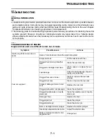
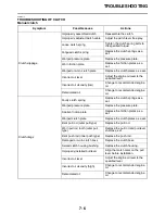
Page 116: ...ficult to start but it cranks Symptom Possible cause Actions Spark plug does not produce a spark Have a Yamaha dealer check the electrical system Fuel not supplied Empty fuel tank Fill the fuel tank with fuel Clogged fuel tank cap breather hole Clean the fuel tank cap Clogged or damaged fuel hose Clean repair or replace the fuel hose Fuel leakage Check the fuel passage Repair or replace as necessa...

Page 117: ...g cap Defective ignition coil Replace the ignition coil CDI unit failure Replace the CDI unit Fuel not supplied Fuel leakage Check the fuel passage Repair or replace as necessary Clogged carburetor fuel passage Clean the carburetor Clogged needle valve or needle valve seat Clean the needle valve or needle valve seat Damaged float Replace the float Water or foreign material in fuel degraded fuel Ch...

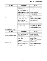
Page 118: ... hose Replace the vacuum hose Damaged carburetor joint Replace the carburetor joint Loose carburetor joint Tighten the carburetor joint bolts to the specified torque Clogged air filter element Clean or replace the air filter ele ment Symptom Possible cause Actions Spark plug does not produce a spark Incorrect spark plug gap Adjust the spark plug gap Worn or damaged spark plug Replace the spark plu...

Page 119: ...ghten the main jet to the speci fied torque Bent damaged or worn jet needle Replace the jet needle Cracks or damage in the piston valve diaphragm Replace the piston valve dia phragm Problem with piston valve move ment movement is not smooth Replace the piston valve Damaged or worn needle valve seat Replace the needle valve seat Loose needle valve seat Tighten the needle valve seat to the specified...

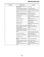
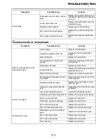
Page 120: ...n rings as a set Worn or damaged piston Replace the piston and piston rings as a set Worn piston piston pin hole Replace the piston and piston pin as a set Worn or damaged piston pin Replace the piston pin Worn or damaged cylinder bore Replace the cylinder piston and piston rings as a set Carbon buildup in piston head and combustion chamber Clean the piston head and com bustion chamber Noise heard...

Page 121: ...ine oil Deteriorated oil Change to recommended engine oil Clutch drags Faulty clutch spring Replace the clutch springs as a set Warped pressure plate Replace the pressure plate Swollen friction plate Replace the friction plates as a set Warped clutch plate Replace the clutch plates as a set Bent pull rod outer pull type Replace the pull rod Worn pull rod tooth outer pull type Replace the pull rod ...

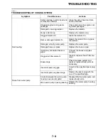
Page 122: ...e the shift drum Seized shift fork Replace the shift fork and shift fork guide bar as a set Bent shift fork guide bar Replace the shift fork guide bar Foreign object between transmis sion gears Remove foreign object from trans mission gears Seized transmission gear Replace the seized gear and the axle as a set Improperly assembled transmis sion Reassemble the transmission axle assembly Jumps out o...

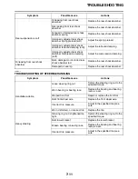
Page 123: ...e the radiator Damaged or faulty water pump Replace the water pump Damaged hoses or pipes Replace the hose or pipe Improperly connected hoses or pipes Connect the hoses and pipes properly Clogged air filter element Clean or replace the air filter ele ment Brake drags Check the brake system and repair or replace faulty parts as necessary Incorrect spark plug gap Adjust to the specified spark plug g...

Page 124: ... Damaged brake hose and brake pipe Replace the brake hose and brake pipe Oil or grease on the brake disc or brake pad Clean the brake disc or brake pad Insufficient lubrication of brake lever or brake pedal pivot Lubricate the brake lever or brake pedal pivot Symptom Possible cause Actions Front fork is hard Bent or damaged inner tube Replace the inner tube Bent or damaged outer tube Replace the o...

Page 125: ...mper rod assembly bolt Tighten the damper rod assembly bolt to the specified torque Damaged damper rod assembly bolt copper washer Replace the damper rod assembly bolt copper washer Cracked or damaged cap bolt O ring Replace the cap bolt O ring Rear suspension is hard Bent or damaged rear shock absorber rod Replace the rear shock absorber Bent swingarm pivot shaft Replace the swingarm pivot shaft ...

Page 126: ... shock absorber rod Replace the rear shock absorber Damaged oil seal lip Replace the rear shock absorber Symptom Possible cause Actions Handlebar wobble Loose steering ring nut Tighten the steering ring nut to the specified torque Worn bearing or bearing race Replace the bearing and bearing race as a set Warped front fork Repair or replace the front fork Bent front wheel axle Replace the front whe...

Page 127: ...que Incorrect front fork oil level Adjust to the specified front fork oil level Rear wheel vibration Incorrect wheel balance Adjust the wheel balance Loose spoke Tighten the spoke and adjust the runout Damaged or worn wheel bearing Replace the wheel bearing Worn deformed or incorrect tire Replace the tire Loose wheel axle nut Tighten the wheel axle nut to the specified torque Loose swingarm pivot ...

Page 128: ...TROUBLESHOOTING 7 13 ...

Page 129: ...DITION AND EXAMPLES OF CARBURETOR SETTING 8 6 EXAMPLES OF CARBURETOR SETTING DEPENDING ON SYMPTOM 8 6 CHANGE OF THE HEAT RANGE OF SPARK PLUGS 8 8 CHASSIS 8 9 SELECTION OF THE SECONDARY REDUCTION RATIO SPROCKET 8 9 DRIVE AND REAR WHEEL SPROCKETS SETTING PARTS 8 9 TIRE PRESSURE 8 9 FRONT FORK SETTING 8 10 CHANGE IN AMOUNT AND CHARACTERISTICS OF FORK OIL 8 10 SETTING OF SPRING AFTER REPLACEMENT 8 10 ...

Page 130: ...ble to make a note of settings atmo spheric conditions road surface condition lap time etc so that the memorandum can be used as a reference useful for future EAM30591 ATMOSPHERIC CONDITIONS AND CARBURETOR SETTINGS The air density i e concentration of oxygen in the air determines the richness or leanness of the air fuel mixture Therefore refer to the above table for mixture settings That is Higher...

Page 131: ...e richness of air fuel mixture under 8500 r min to the extent of 1 2 to full opened throttle can be set by changing the power jet 1 A larger size jet results in a richer mixture and a smaller size in a leaner mixture EAM30595 PILOT AIR SCREW ADJUSTMENT The richness of the air fuel mixture with the throttle fully closed to 1 8 open can be set by turning the pilot air screw 1 Turning in the pilot ai...

Page 132: ...e taper angle are available in different straight portion diameters and in different taper start ing positions 2 Effects of changing the jet needle reference Diameter of straight portion Changing the diameter of the straight portion adjusts the air fuel mixture when the throttle is 1 8 to 1 4 open Taper starting position Changing the taper starting position produc es the same effect as changing th...

Page 133: ...lip by one groove and move up the needle to enrich the mixture EAM30605 RELATIONSHIP WITH THROTTLE OPENING The flow of the fuel through the carburetor main system is controlled by the main jet and then it is further regulated by the area between the main nozzle and the jet needle On the relation ship between the fuel flow and the throttle open ing the fuel flow relates to the jet needle straight p...

Page 134: ...ean 162 4MX 14943 90 Pilot jet 2 Rich 62 4MX 14948 12 60 4MX 14948 11 58 4MX 14948 10 55 4MX 14948 09 52 4MX 14948 08 STD 50 4MX 14948 07 48 4MX 14948 06 45 4MX 14948 05 42 4MX 14948 04 40 4MX 14948 03 Lean 38 4MX 14948 02 Jet needle 3 Rich N8RH 4SR 14916 RH N3EH 4SR 14916 EH N8RW 4SR 14916 RW STD N3EW 4SR 14916 EW N3CW 4SR 14916 CW N3EJ 4SR 14916 EJ Lean N3CJ 4SR 14916 CJ Power Jet 4 Rich 65 4JT ...

Page 135: ... 2 N3CW 3 N3CW 3 N3CW 3 N3EW 3 N3CW 3 N3EW 2 N3CW 4 N3EW 3 N3EW 3 Pilot jet 50 50 50 52 52 52 Pilot air screw 1 4 0 0 0 0 1 4 Power jet 50 50 50 50 50 50 Symptom Setting Checking At full throttle Stall at high speeds Hard breathing Shearing noise Whitish spark plug Lean mixture Increase main jet calibration no Gradually Discoloration of spark plug If tan color it is in good condition If cannot be ...

Page 136: ...s the jet needle groove on which the clip is installed The positions are numbered from the top Closed to 1 4 throttle Hard breathing Speed down Use jet needle having a smaller diam eter Closed to 1 4 throttle Poor acceleration White smoke Use jet needle with a larger diameter Unstable at low speeds Pinking noise Lower jet needle clip position 1 groove down Turn in pilot air screw Poor response at ...

Page 137: ... No of the main jet must be changed by 30 it is advisable to change the heat range of spark plugs and newly select the proper main jet TIP When checking the discoloration of spark plugs be sure to stop the engine immediately after a run and check Avoid racing When changing the heat range of spark plugs never attempt to change it more than 1 rank When using a spark plug other than standard check it...

Page 138: ...t such that it can develop its maximum revolutions toward the end of the straight line with care taken to avoid the en gine over revving TIP Riding technique varies from rider to rider and the performance of a machine also vary from machine to machine Therefore do not imitate other rider s settings from the beginning but choose your own setting according to the level of your riding technique EAM30...

Page 139: ...r spring characteristics to have a ten dency to be stiffer with the consequent dete riorated performance and characteristics Therefore adjust the front fork within the specified range EAM30173 SETTING OF SPRING AFTER REPLACEMENT As the front fork setting can be easily affected by the rear suspension take care so that the front and the rear are balanced in position etc when setting the front fork 1...

Page 140: ...orce EAM30176 CHOOSING SET LENGTH 1 Place a stand or a block under the engine to put the rear wheel above the floor and mea sure the length a between the rear wheel axle center and the rear fender holding bolt 2 Remove the stand or block from the engine and with a rider astride the seat measure the sunken length b between the rear wheel axle center and the rear fender holding bolt 3 Loosen the loc...

Page 141: ...or correction adjust to decrease compression damping force WARNING EWA19200 When using a rear shock absorber other than currently installed use the one whose overall length a does not exceed the stan dard as it may result in faulty performance Never use one whose overall length is great er than standard EAM30178 REAR SHOCK ABSORBER SETTING PARTS Rear shock spring 1 Equal pitch steel spring Unequal...

Page 142: ...HE REAR SHOCK ABSORBER AS SEMBLY on page 3 21 Spring preload adjusting positions Minimum Position in which the spring is turned in 1 5 mm 0 06 in from its free length Standard Position in which the spring is turned in 12 0 mm 0 47 in from its free length Maximum Position in which the spring is turned in 18 0 mm 0 71 in from its free length ...

Page 143: ...oticeable scars etc If any replace affected parts Slide metal Replace with a new one for extended use Piston metal Replace with a new one for extended use Lower bracket tightening torque Retighten to specified torque Poor initial move ment Rebound damp ing force Turn adjuster counterclockwise about 2 clicks to decrease damping Oil seals Apply grease in oil seal wall Soft over entire range bottomin...

Page 144: ...ount Increase oil amount by about 5 cm 0 2 US oz 0 2 Imp oz Obtrusive front tending to upper front posture Compression damping force Turn adjuster counterclockwise about 2 clicks to decrease damping Balance with rear end Set sunken length for 90 95 mm 3 5 3 7 in when one passenger is astride seat upper rear pos ture Spring Replace with soft spring Oil amount Decrease oil amount by about 5 10 cm 0 ...

Page 145: ... senger is astride seat Spring Replace with soft spring Bottoming out High compres sion damping Turn adjuster clockwise about 1 6 turn to increase damping Spring set length Set sunken length for 90 100 mm 3 5 3 9 in when one pas senger is astride seat Spring Replace with stiff spring Bouncing Rebound damp ing force Turn adjuster clockwise about 2 clicks to increase damping Spring Replace with soft...

Page 146: ...CHASSIS 8 17 ...

Page 147: ...riginally equipped on your vehicle providing you with the performance and durability you have come to expect Why settle for aftermarket parts that may not provide full confidence and satisfaction Genuine Yamaha Accessories Yamaha only offers accessories that meet our high standards for quality and performance Buy with confidence knowing your Genuine Yamaha Accessories will fit right and perform ri...

Page 148: ...99 10 LIT 11626 34 11 Read this manual carefully before operating this vehicle YZ250M2 YZ250XM OWNER S MANUAL YZ250 YZ250X 2021 PRINTED IN JAPAN 2020 04 0 9 1 E BF1 28199 10_cover indd 1 3 2020 03 10 13 38 50 ...

Reviews: