background image

– 47 –

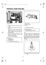
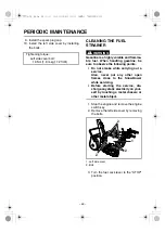
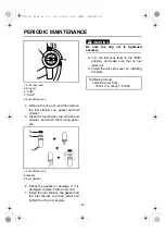
1. Spark plug cap

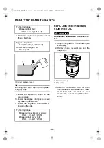
4. Remove the spark plug using a plug

wrench.

5. Check the spark plug for any signs of

burns.
Burn marks on spark plugs are usually
medium-to-light tan. If there are any
black or white burn marks, consult your
Yamaha dealer.

6. Remove deposits (carbon) from the

spark plug electrode using a plug
cleaner or a wire brush.

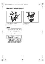
7. Check the spark plug gap.

1. Spark plug gap
2. Spark plug number
3. Insulator

8. Install the spark plug.

TIP

If a torque wrench is not available when
installing a spark plug, a good estimate of
the correct torque is 1/4–1/2 turn past finger
tight. However, the spark plug should be
tightened to the specified torque as soon as
possible.

1. Fully tighten the spark plug using your fingers.
2. 1/4–1/2 turn

Spark plug: 

NGK BPR4ES

Spark plug gap: 

0.7–0.8 mm (0.028–0.031 in)

1

Tightening torque:

18 Nm (1.8 m·kgf, 13 ft·lbf)

1

2

3

1

2

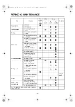
PERIODIC MAINTENANCE

7VY-9-70_E0.fm  47 ページ  2010年4月30日 金曜日 午前9時35分

Summary of Contents for YS928J

Page 1: ...Read this manual carefully before operating this machine 7VY 28199 70 YS928J Snowblower OWNER S MANUAL 7VY 9 70_hyo indd 1 2010 05 07 9 19 39 ...

Page 2: ...ts rear side and keep the card in a safe place This is the safety alert symbol It is used to alert you to potential personal injury hazards Obey all safety messages that follow this symbol to avoid possible injury or death A WARNING indicates a hazardous situation which if not avoided could result in death or serious injury A NOTICE indicates special precautions that must be taken to avoid damage ...

Page 3: ...TOR OPERATION 29 CHECKING THE ENGINE FOR POOR STARTING OR ABNORMAL NOISE 29 CHECKING THE EXHAUST SYSTEM 29 CHECKING THE AUGER CLUTCH AND DRIVE CLUTCH FOR OPERATION MALFUNCTION 29 CHECKING THE CHUTE OPERATION 29 CHECKING ANY TROUBLES NOTICED WHEN PREVIOUSLY OPERATING THE SNOWBLOWER 29 OPERATION 30 STARTING THE ENGINE 30 STOPPING THE ENGINE 32 MOVING THE SNOWBLOWER 32 CLEARING SNOW 34 STOPPING CLEAR...

Page 4: ...CHECKING THE BATTERY FLUID 56 REPLACING THE FUSE 57 LUBRICATING EACH PART 58 STORAGE 59 SHORT TERM 59 LONG TERM 63 SPECIFICATIONS 64 INDEX 65 CONTENTS 7VY 9 70_E0 fm 0 ページ 2010年4月30日 金曜日 午前9時35分 ...

Page 5: ...product name and the serial number columns at right Also record the product name and product serial number separately in case of theft or emergency 1 Product serial number label 1 Product name 2 Product serial number 1 1 2 Product name Product serial number Date of purchase Purchased from Phone PRODUCT SERIAL NUMBER LABEL 7VY 9 70_E0 fm 1 ページ 2010年4月30日 金曜日 午前9時35分 ...

Page 6: ...hildren or anyone who does not understand how to operate the Snow blower correctly to operate it Never operate the Snowblower when you are tired or under the influence of alcohol or drugs Wear non slip footwear warm clothing and gloves when operating the Snowblower Do not operate the Snowblower in low visi bility conditions such as early morning and night time 1 SAFETY INFORMATION 7VY 9 70_E0 fm 2...

Page 7: ...gine indoors except when you are moving the Snowblower Exhaust fumes contain harmful chemicals such as carbon monoxide Open the door and adequately ventilate the building even when you are moving the Snowblower Gasoline is a highly flammable and easily ignitable fuel Always turn off the engine and avoid open flame while filling the fuel tank 3 2 1 S SAFETY INFORMATION 7VY 9 70_E0 fm 3 ページ 2010年4月3...

Page 8: ...own together with snow 1 Auger housing 2 Clearance Do not allow anyone except the operator of the Snowblower near the place you wish to clear snow from Do not look in the rotating parts such as the auger and impeller or in the chute or put your face arms or legs near such parts 1 Auger 2 Impeller 3 Chute Do not blow snow toward people buildings automobiles etc Do not blow snow across the face of a...

Page 9: ...intenance When you park the Snowblower stop it on a flat surface and lower auger onto the ground Then place shift lever in a position other than N Neutral 1 Auger 2 Shift lever The muffler exhaust pipe will still be hot immediately after the engine has stopped Place the Snowblower in a place where pedestrians are not likely to touch the Snowblower 1 2 SAFETY INFORMATION 7VY 9 70_E0 fm 5 ページ 2010年4...

Page 10: ...w To dislodge snow from the chute stop the engine and use the clean out tool 1 Chute To attach a cover or similar device to the Snowblower wait until the engine and muf fler have completely cooled down 1 SAFETY INFORMATION 7VY 9 70_E0 fm 6 ページ 2010年4月30日 金曜日 午前9時35分 ...

Page 11: ...abels affixed to the machine and use according to the instructions on the labels TIP If these important labels are damaged or missing contact your Yamaha dealer for replace ments LOCATION OF IMPORTANT LABELS 2 1 7VY 9 70_E0 fm 7 ページ 2010年4月30日 金曜日 午前9時35分 ...
Page 12: ... 8 LOCATION OF IMPORTANT LABELS 3 4 5 7VY 2179R 00 6 7 7VY 9 70_E0 fm 8 ページ 2010年4月30日 金曜日 午前9時35分 ...
Page 13: ...Transmission HST oil reservoir 4 Muffler 5 Fuel cock 6 Left side cover 7 Track 8 Auger 9 Impeller 10 Auger housing 11 Clean out tool lodged snow remover 12 Side marker snow slicer 8 9 10 11 12 1 2 3 4 5 6 7 7VY 9 70_E0 fm 9 ページ 2010年4月30日 金曜日 午前9時35分 ...
Page 14: ... 10 1 Working light 2 Right side cover 3 Engine oil inspection cover 4 Scraper 5 Skid 6 Control panel 7 Handlebar 7 7 6 5 4 3 2 1 DESCRIPTION 7VY 9 70_E0 fm 10 ページ 2010年4月30日 金曜日 午前9時35分 ...

Page 15: ...e lever 7 Oil level warning light 8 Auger housing height control lever 9 Engine switch 1 Fuel cock lever 2 RUN 3 STOP 4 Fuel cock 5 CARBURETOR DRAIN 6 HOSE DRAIN 1 Fuel gauge 2 Fuel tank cap 3 Fuel tank 7 5 4 1 2 3 6 9 8 RUN S T O P H O S E CARBURETOR D R AIN 1 4 2 5 6 3 1 3 2 DESCRIPTION 7VY 9 70_E0 fm 11 ページ 2010年4月30日 金曜日 午前9時35分 ...
Page 16: ... 12 1 Fuse 2 Electric starter 3 Engine oil filler cap 4 Engine oil drain bolt 2 1 4 3 DESCRIPTION 7VY 9 70_E0 fm 12 ページ 2010年4月30日 金曜日 午前9時35分 ...
Page 17: ... 13 1 Spark plug cap Spark plug 2 Carburetor 3 Air filter 4 Fuel drain hose 5 Fuel strainer cup 6 Fuel cock lever 1 2 3 4 5 6 DESCRIPTION 7VY 9 70_E0 fm 13 ページ 2010年4月30日 金曜日 午前9時35分 ...
Page 18: ...er motor cranks the engine When releasing the grip the key returns to the ON position automatically The key cannot be removed NOTICE Do not continue to use the starter motor for more than 5 seconds Doing so will consume a large amount of power and it may exhaust the battery Do not leave the key in the ON position for a long time while the engine is stopped It may exhaust the battery TIP Remove the...

Page 19: ...pecified level TIP The oil level warning light may come on when the Snowblower is tilted excessively If so park the Snowblower on a level sur face and check if the oil level warning light comes on THROTTLE LEVER 1 Throttle lever 2 FAST START 3 SLOW Controls the engine speed FAST START Lever position to start the engine and to start snow clearing or moving SLOW Lever position to idle the engine 1 2...

Page 20: ...the direction that snow is blown Move the chute direction control lever to the right The chute rotates clockwise Move the chute direction control lever to the left The chute rotates counterclockwise NOTICE Do not press the chute direction control lever forcefully Doing so may damage the switch When the chute is locked do not continue to press the chute direc tion control lever If you do so the mot...

Page 21: ...UTE DEFLECTOR CONTROL LEVER 1 Chute deflector control lever 2 Pull 3 Push 4 Chute deflector 5 Upward 6 Downward Used to change the angle that snow is blown Pull the chute deflector control lever The chute deflector moves upward to blow snow long distances Push the chute deflector control lever The chute deflector moves downward to blow snow nearby 2 3 5 4 1 6 CONTROL FUNCTION 7VY 9 70_E0 fm 17 ページ...

Page 22: ...lever The Snowblower stops traveling AUGER CLUTCH LEVER 1 Auger clutch lever Used to rotate the auger Pull the auger clutch lever The auger rotates TIP It is impossible to pull the auger clutch lever if the drive clutch lever is released Push the auger clutch lever The auger stops rotating 1 1 CONTROL FUNCTION 7VY 9 70_E0 fm 18 ページ 2010年4月30日 金曜日 午前9時35分 ...
Page 23: ...sing height control lever at the desired auger height To lower the auger housing Pull and hold the auger housing height con trol lever and return the handlebar to its original position Then release the auger housing height control lever FUEL TANK CAP 1 Fuel tank cap Turn the fuel tank cap counterclockwise to remove WARNING After refueling make sure the fuel tank cap is tightened securely 1 1 CONTR...

Page 24: ...ition when the Snowblower is not being used CARBURETOR DRAIN Move the fuel cock lever to this position to drain the fuel from the carburetor i e when storing or when the Snowblower will not be used for a long period of time HOSE DRAIN Move the fuel cock lever to this position to drain the fuel in the fuel hose between the fuel cock and the carburetor i e when storing or when the Snowblower will no...

Page 25: ...to road surface conditions see page 50 NOTICE If the clearance between the road sur face and the auger end is too small auger wear may increase and the road surface could be damaged Fuse capacity 30 A blade type fuse 1 2 3 Clearance between the auger end and the road surface Factory set Standard position 5 mm 0 197 in Concrete and asphalt roads Decrease Pebble and gravel roads Increase 1 2 4 3 CON...

Page 26: ...guard will run idle to absorb the impact and protect the auger If any bigger impact is added to the auger the shear bolt will break to protect the auger and auger shaft WARNING Do not look in or put your hands near the auger when it is rotating NOTICE Use genuine shear bolts when replac ing Clearance between the road surface and the scraper end Factory set Standard position 5 mm 0 197 in or more C...

Page 27: ... auger WARNING Do not look in or put your hands near the impeller or auger when they are rotating When removing snow lodged in a rotating part stop the engine remove the engine switch key and wait until all moving parts have stopped Wear gloves when using the clean out tool lodged snow remover 1 2 1 2 CONTROL FUNCTION 7VY 9 70_E0 fm 23 ページ 2010年4月30日 金曜日 午前9時35分 ...
Page 28: ...L FUNCTION WORKING LIGHT 1 Working light When starting the engine the working light comes on automatically and illuminates the front of the Snowblower Bulb 12 V 23 W 1 7VY 9 70_E0 fm 24 ページ 2010年4月30日 金曜日 午前9時35分 ...
Page 29: ...itch key The engine and muffler will still be very hot immediately after the engine is stopped Conduct checks or maintenance after the engine and muffler have completely cooled down If any abnormalities are discovered carry out maintenance by yourself or have a Yamaha dealer perform it for you CHECK BEFORE USE For safe and comfortable use of your Snow blower always check the following items before...

Page 30: ... bodies may cause a spark Only refuel outdoors Do not fill gasoline above the speci fied level up to the base of the filler neck If any gasoline spills wipe it up completely using dry rags After refueling make sure the fuel tank cap is tightened securely Should you happen to swallow some gasoline inhale gasoline vapor or get gasoline in your eyes seek immediate medical attention If any gasoline sp...

Page 31: ...the engine oil is below the correct engine oil level fill up to the brim of the oil filler hole with the recommended engine oil TIP If the engine oil spills wipe it up immedi ately using dry rags 6 Install and tighten the engine oil filler cap securely 7 Install the engine oil inspection cover see page 43 1 1 1 Recommended brand YAMALUBE Type SAE 5W 30 Recommended engine oil grade API Service SE t...

Page 32: ...ity changes due to thermal expansion or con traction When the ambient temperature is low below approx 20 C or before operating the Snowblower you may not be able to see the level of transmission HST oil in the oil reservoir This is normal When you start snow blowing the transmis sion will warm up and you will be able to see the oil level 3 When the transmission HST oil drops below the minimum leve...

Page 33: ...e coming from the engine CHECKING THE EXHAUST SYSTEM After starting the engine check the exhaust system for any abnormalities CHECKING THE AUGER CLUTCH AND DRIVE CLUTCH FOR OPERATION MALFUNC TION After starting the engine operate both auger clutch lever and drive clutch lever Release each lever and make sure that the auger stops rotating and that the Snow blower stops see page 34 1 Auger clutch le...

Page 34: ...ever 2 Turn the fuel cock lever from the STOP position to the RUN position 1 RUN 2 STOP 3 Fuel cock lever 3 Move the throttle lever to the FAST START position TIP If the engine is already warmed up it is not necessary to move the throttle lever to the FAST START position 1 Throttle lever 2 FAST START 3 SLOW 4 Start the engine by turning the engine switch key to the START position When the engine h...

Page 35: ...witch key to an inter mediate position between the STOP and ON positions and check whether or not the engine oil warning light comes on If not the bulb of the oil level warning light may have been burnt out In this case contact your Yamaha dealer for service If the engine fails to start within 5 sec onds after turning the engine switch return the key to the STOP position and wait for 10 seconds to...

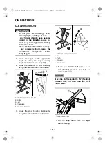
Page 36: ...R 1 Use the auger housing height control lever to raise the auger to the highest position 1 Auger housing height control lever 2 Auger housing 2 Make sure that the shift lever is in the N Neutral position and move the throttle lever to the FAST START position 1 Shift lever 2 N Neutral 1 2 RUN S T O P H O S E CARBURETOR D R AIN 3 1 2 1 2 1 2 OPERATION 7VY 9 70_E0 fm 32 ページ 2010年4月30日 金曜日 午前9時35分 ...
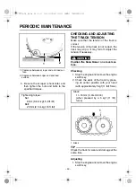
Page 37: ...e N Neu tral position and then hold the drive clutch lever Operate the drive clutch lever slowly 1 Drive clutch lever 4 Slowly move the shift lever from N Neutral position to forward or reverse NOTICE Operate the shift lever slowly 1 Shift lever 2 N Neutral 2 1 3 1 1 1 2 OPERATION 7VY 9 70_E0 fm 33 ページ 2010年4月30日 金曜日 午前9時35分 ...
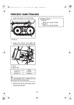
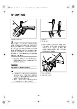
Page 38: ...e direction to blow snow by using the chute direction control lever 1 Chute direction control lever 2 Right 3 Left 4 Clockwise 5 Counter clockwise 3 Adjust the snow blowing distance by using the chute deflector control lever 1 Chute deflector control lever 2 Pull 3 Push 4 Upward 5 Downward 4 Make sure that the shift lever is in the N Neutral position and hold the drive clutch lever NOTICE Move the...

Page 39: ...u tral position to the F Forward or R Reverse position NOTICE Operate the shift lever slowly TIP If the engine speed drops excessively and snow is not being blown properly you may be driving the Snowblower too quickly Reduce the speed Snow is blown more effectively when the Snowblower is driven slowly 1 Shift lever 2 N Neutral 7 When releasing the drive clutch lever the auger clutch lever automati...

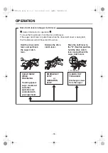
Page 40: ...e drive clutch lever To move the Snowblower hold the drive clutch lever If the auger clutch lever is pulled back while the drive clutch lever is being held the Snowblower will still travel and blow snow CLEAR SNOW WHILE TRAVELING Traveling speed auger movement and other operations are controlled with your right hand EMERGENCY STOP or OPERATION STOP CLEANS OUT THE AUGER Discharges snow from the aug...

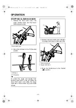
Page 41: ... TIP To protect the auger and impeller from freezing allow them to idle by holding the drive clutch lever and pulling the auger clutch lever This will clear any snow inside of them 3 Release the drive clutch lever Release the auger clutch lever at the same time 1 Drive clutch lever 2 Auger clutch lever 4 Move the throttle lever to the SLOW position 1 1 2 1 2 OPERATION 7VY 9 70_E0 fm 37 ページ 2010年4月...

Page 42: ...ngine Position the Snowblower on a level surface before beginning the follow ing procedure 1 Ring 2 Sprocket pin 3 Hole 4 Sprocket wheel 1 Remove the sprocket pin from the wheel by pulling on the ring 2 Insert the sprocket pin into the hole of the wheel axle 3 Fold the ring of the sprocket pin down ward to lock it The sprocket wheel is now freed from the wheel axle TIP Repeat steps 1 to 3 for the ...

Page 43: ... from the wheel axle and insert them into the hole of each wheel and then fold the ring of the sprocket pin downward to lock it NOTICE Do not hammer the sprocket pins Always fold and close the ring 7VY 9 70_E0 fm 39 ページ 2010年4月30日 金曜日 午前9時35分 ...
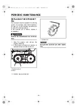
Page 44: ...CHECK BEFORE USE The customer needs to perform the routine inspection see page 25 If any problems are dis covered during the inspection contact your Yamaha dealer and request an inspection or maintenance PERIODIC INSPECTION Yamaha dealers perform periodic inspections when requested by the customer The customer is responsible for contacting their Yamaha dealer to request a periodic inspec tion Init...

Page 45: ...ths Handlebar Looseness and play Skid Mounting and parallel layout Auger height control Working conditions Engine switch Working conditions Check for burnt out bulb of oil level warning light Controls Auger switch operation and working conditions Shift lever operation Shift lever adjustment status Drive clutch operation Auger and impeller Mounting status and bending Chute Working conditions Chute ...

Page 46: ...ting system Oil leakage Engine oil level Engine oil change Fuel system Fuel leakage Carburetor throttle valve and choke valve conditions Carburetor adjustment conditions Fuel level Fuel hose replacement Every 4 years Muffler Check mounting for looseness Muffler condition Chassis and moving parts Damage including cracks and loose parts Lubricating each part Any troubles noticed when previously oper...

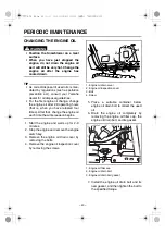
Page 47: ...son begins 1 Start the engine and warm up for 2 3 minutes 2 Stop the engine and remove the engine switch key 3 Remove the engine oil drain cover by removing the bolts 4 Remove the engine oil inspection cover by removing the screws 1 Engine oil drain cover 2 Engine oil inspection cover 3 Bolt 4 Screw 5 Place a suitable container below engine oil drain bolt to collect the used oil 6 Drain the engine...

Page 48: ...Stop the engine and remove the engine switch key 2 Remove the oil reservoir cap and the diaphragm 1 Oil reservoir cap 2 Diaphragm 3 Refill the transmission HST oil to an intermediate level between the maxi mum level mark and minimum level mark of the transmission HST oil res ervoir Tightening torque Engine oil drain bolt 30 Nm 3 0 m kgf 21 ft lbf Engine oil quantity 1 0 L 1 06 US qt 0 88 Imp qt Re...

Page 49: ... Use the recommended transmis sion HST oil only 4 Install the diaphragm so that its notch is aligned with the notch on the trans mission HST oil reservoir and then tighten the oil reservoir cap securely 1 Alignment mark 2 Diaphragm 3 Oil reservoir cap Recommended transmission HST oil Diesel engine oil 10W 30 Class CD or higher 1 2 3 4 3 2 1 PERIODIC MAINTENANCE 7VY 9 70_E0 fm 45 ページ 2010年4月30日 金曜日...

Page 50: ... falls over time and according to how it is used periodic inspections involving removal of the spark plug are required WARNING The engine and muffler will still be very hot immediately after the engine is stopped Exercise care not to burn yourself When removing or installing the spark plug exercise care not to damage its insulator Poor electrical insulation could cause high voltage leaks resulting...

Page 51: ...gap 1 Spark plug gap 2 Spark plug number 3 Insulator 8 Install the spark plug TIP If a torque wrench is not available when installing a spark plug a good estimate of the correct torque is 1 4 1 2 turn past finger tight However the spark plug should be tightened to the specified torque as soon as possible 1 Fully tighten the spark plug using your fingers 2 1 4 1 2 turn Spark plug NGK BPR4ES Spark p...

Page 52: ... other open flames close to the Snowblower while servicing Before starting the service dis charge any static electricity on your self by touching a metal chassis or other metal object 1 Stop the engine and remove the engine switch key 2 Remove the left side cover by removing the bolts 1 Left side cover 2 Bolt 3 Turn the fuel cock lever to the STOP position Tightening torque Left side cover bolt 10...

Page 53: ... damage If it is damaged replace it with a new one 7 Install the fuel strainer the gasket and the fuel strainer cup then install and tighten the ring nut securely WARNING Be sure the ring nut is tightened securely 8 Turn the fuel cock lever to the RUN position and make sure that no fuel leaks out 9 Install the left side cover by installing the bolts 1 2 5 3 3 4 1 2 3 Tightening torque Left side co...

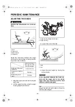
Page 54: ...l lever 2 Auger housing 3 Loosen the nuts of the skid 1 Skid 2 Nut 4 Adjust the skid height by moving the skid vertically NOTICE If the clearance between the road sur face and the auger end is too small auger wear may increase and the road surface could be damaged TIP Adjust the left and right skids so they are both the same height Clearance between the auger end and the road surface Factory set S...

Page 55: ...nowblower on a level surface Wear gloves when using the clean out tool lodged snow remover 1 Stop the engine and remove the engine switch key 2 Be sure to use the clean out tool lodged snow remover to remove snow and other obstacles from the auger housing 3 Remove the lock nuts the shear bolts and the washers 1 Lock nut 2 Shear bolt 3 Washer 4 Install the new shear bolts with their washers Tighten...

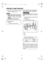
Page 56: ...e the engine switch key 2 Loosen the nuts 3 Loosen the left and right bolts 1 Bolt 2 Nut 3 Scraper 4 Adjust the clearance to the road sur face by moving the scraper TIP Adjust the clearance between the scraper end and the road surface so that it becomes equal to or greater than the clear ance between the auger end and the road surface Tightening torque Lock nut 19 Nm 1 9 m kgf 13 ft lbf Clearance ...

Page 57: ...ion if necessary WARNING Position the Snowblower on a level sur face Checking 1 Stop the engine and remove the engine switch key 2 Check the slack of the track by press ing its center position with your hand with approximately 5 kgf 11 lbf force 1 Slack TIP Check the track for wear and damage at the same time Adjusting 1 Stop the engine and remove the engine switch key Tightening torque Nut 8 Nm 0...

Page 58: ... TIP Turn the adjusting bolts so that the left and right tracks have the same slack 4 Tighten the locknuts and wheel nuts to the specified torques Slack Direction A Increase Direction B Decrease 1 A 1 2 B Tightening torque Locknut 25 Nm 2 5 m kgf 18 ft lbf Wheel nut 53 Nm 5 3 m kgf 38 ft lbf PERIODIC MAINTENANCE 7VY 9 70_E0 fm 54 ページ 2010年4月30日 金曜日 午前9時35分 ...
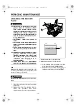
Page 59: ...cket pin is broken replace it immediately WARNING Position the Snowblower on a level sur face 1 Stop the engine and remove the engine switch key 2 If the broken sprocket pin remains in sprocket wheel or shaft remove it 1 Sprocket wheel 2 Shaft 3 Install a new sprocket pin 1 Sprocket pin NOTICE Use genuine sprocket pin when replac ing 1 2 1 PERIODIC MAINTENANCE 7VY 9 70_E0 fm 55 ページ 2010年4月30日 金曜日 ...

Page 60: ...tc away from the battery and provide sufficient ventilation when charging it in an enclosed space KEEP THIS AND ALL BATTERIES OUT OF THE REACH OF CHILDREN TIP Measure the specific gravity must be 1 28 or more periodically every 6 months and check the battery conditions WARNING Position the Snowblower on a level sur face 1 Stop the engine and remove the engine switch key 2 Make sure that the batter...

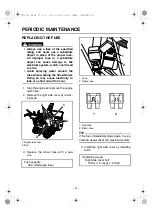
Page 61: ...ricity to leak or a short circuit to occur 1 Stop the engine and remove the engine switch key 2 Remove the right side cover by remov ing bolts 1 Right side cover 2 Bolt 3 Replace the blown fuse with a new one 1 Fuse 2 Spare fuse 1 New fuse 2 Blown fuse TIP If the fuse immediately blows again have a Yamaha dealer check the electrical system 4 Install the right side cover by installing bolts Fuse ca...

Page 62: ...ver Shift lever moving parts Chute assembly moving parts Chute motor gears and ring gears Drive clutch lever moving parts Auger clutch lever moving parts Throttle lever moving parts 1 Moving parts of chute deflector control lever 2 Shift lever moving parts 3 Drive clutch lever moving parts 4 Auger clutch lever moving parts 5 Throttle lever moving parts 1 2 3 4 5 PERIODIC MAINTENANCE 7VY 9 70_E0 fm...

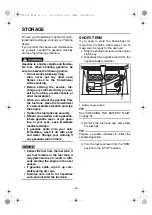
Page 63: ...es seek immediate medical attention If gasoline spills onto your skin immediately wash it off with soap and water Change your clothing if any gasoline spills on them NOTICE Extract the fuel from the fuel tank If any fuel remains in the fuel tank it may deteriorate and result in diffi culty starting the engine in the next season If gasoline spills wipe it up com pletely using dry rags Exercise care...

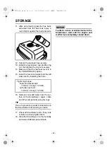
Page 64: ...w the fuel cock to collect the drained gaso line Remove the ring nut of the fuel cock and then remove the fuel strainer cup 1 Ring nut 2 Fuel strainer cup 3 Container TIP If the ring nut is too tight loosen it using a wrench or other tool 8 Turn the fuel cock lever from the STOP position to the RUN position and drain the remaining gasoline out of the fuel tank 1 2 3 1 2 2 2 1 1 2 1 2 3 STORAGE 7VY...

Page 65: ...in hose 1 Container 2 Fuel drains from here 10 Turn the fuel cock lever from the CAR BURETOR DRAIN position to the HOSE DRAIN position Drain the gas oline from the hose through the fuel drain hose 1 HOSE DRAIN 2 CARBURETOR DRAIN 3 Fuel cock lever 4 Fuel drain hose NOTICE Immediately wipe off spilled fuel with a clean dry soft cloth since fuel may deteriorate painted surfaces or plastic parts 1 4 3...

Page 66: ...now and water from the sur face of the Snowblower auger chute and other components using dry rags TIP This is to prevent any water that remains on the Snowblower from causing corrosion 17 Check all Snowblower parts If any nuts or bolts are loose tighten them 18 Store the Snowblower in a low humidity and well ventilated space indoors NOTICE To attach a cover or similar device to the Snowblower wait...

Page 67: ...e steps below to keep it in good condition 1 Follow steps 1 17 under SHORT TERM 2 Clean each part of the Snowblower and implement rust treatment 3 Place a cover on the Snowblower and store it in a low humidity and well venti lated space indoors 7VY 9 70_E0 fm 63 ページ 2010年4月30日 金曜日 午前9時35分 ...
Page 68: ...3 Maximum output 6 3 kW 8 5 PS 4000 r min Recommended fuel Unleaded regular gasoline Fuel tank capacity 6 7 L 1 77 US gal 1 47 Imp gal Lubrication system Wet sump forced spray type Recommended engine oil YAMALUBE SAE 5W 30 API Service SE type or higher Engine oil quantity 1 0 L 1 06 US qt 0 88 Imp qt Recommended transmission HST oil Diesel engine oil 10W 30 Class CD or higher Transmission HST oil ...

Page 69: ...L LEVEL 26 CHECKING THE HANDLEBAR FOR LOOSENESS OR PLAY 29 CHECKING THE STARTER MOTOR OPERATION 29 CHECKING THE TRANSMISSION HST OIL 28 CHUTE DEFLECTOR CONTROL LEVER 17 CHUTE DIRECTION CONTROL LEVER 16 CLEANING THE FUEL STRAINER 48 CLEAN OUT TOOL LODGED SNOW REMOVER 23 CLEARING SNOW 34 CONTROL FUNCTION 14 D DESCRIPTION 9 DRIVE CLUTCH LEVER 18 E ENGINE SWITCH 14 F FUEL COCK 20 FUEL GAUGE 20 FUEL TA...

Page 70: ... SAFETY INFORMATION 2 SCRAPER 22 SHEAR BOLT GUARD 22 SHIFT LEVER 16 SKID 21 SPECIFICATIONS 64 STARTING THE ENGINE 30 STOPPING CLEARING SNOW 37 STOPPING THE ENGINE 32 STORAGE 59 T THROTTLE LEVER 15 W WORKING LIGHT 24 INDEX 7VY 9 70_E0 fm 66 ページ 2010年4月30日 金曜日 午前9時35分 ...

Reviews: