background image

YDP-131/YDP-131C

3

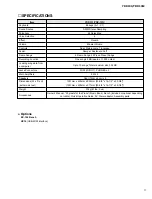
 SPECIFICATIONS

Item

Keyboard

Sound Source

Polyphony

Voice Selection

Effect

Volume

Controls

Pedal

Demo Songs

Recording Function

Loading song data from

a computer

Jacks/Connectors

Main Amplifiers

Speakers

Dimensions (W x D x H)

(with music rest)

Weight

Accessories

YDP-131/YDP-131C

88 keys (A-1 - C7)

AWM Stereo Sampling

64 Notes Max.

6

Reverb

Master Volume

Dual, Metoronome, Transpose

Damper, Sostenuto, Soft

6 Demo Songs, 50 Piano Preset Songs

One song 65 KB (approx. 11,000 notes)

Up to 10 songs; Total maximum size 352 KB

MIDI (IN/OUT), PHONES x 2

6W x 2

Oval (12cm x 6cm) x 2

1357mm x 420mm x 822mm [53-3/8" x 16-1/2" x 32-3/8"]

(1357mm x 420mm x 971mm [53-3/8" x 16-1/2" x 38-1/4"])

37kg (81lbs., 9oz)

Owner’s Manual, “50 greats for the Piano” (Music Book), Bench (included or optional depending

on locale), Quick Operation Guide, AC Power adaptor, Assembly parts

Options

BC-104 Bench

UX16 (USB-MIDI interface)

Summary of Contents for YDP-131

Page 1: ... UP DATA AND INITIALIZING THE SETTINGS バックアップデータと初期化 42 43 TRANSMITTING SONG DATA BETWEEN THE COMPUTER AND YDP 131 YDP 131C YDP 131 YDP 131Cとコンピューター間でのデータの送受信 44 45 MIDI IMPLEMENTATION CHART 46 MIDI DATA FORMAT 47 PARTS LIST BLOCK DIAGRAM ブロックダイアグラム CIRCUIT BOARD LAYOUT WIRING ユニットレイアウト 結線図 OVERALL CIRCUIT DIAGRAM 総回路図 Copyright c Yamaha Corporation All rights reserved PDF 06 08 PK 000398 YDP 131 ...

Page 2: ...can destroy expensive components Discharge any static electricity your body may have accumulated by grounding yourself to the ground bus in the unit heavy gauge black wires connect to this bus IMPORTANT Turn the unit OFF during disassembly and parts replacement Recheck all work before you apply power to the unit WARNING CHEMICAL CONTENT NOTICE The solder used in the production of this product cont...

Page 3: ...ax 6 Reverb Master Volume Dual Metoronome Transpose Damper Sostenuto Soft 6 Demo Songs 50 Piano Preset Songs One song 65 KB approx 11 000 notes Up to 10 songs Total maximum size 352 KB MIDI IN OUT PHONES x 2 6W x 2 Oval 12cm x 6cm x 2 1357mm x 420mm x 822mm 53 3 8 x 16 1 2 x 32 3 8 1357mm x 420mm x 971mm 53 3 8 x 16 1 2 x 38 1 4 37kg 81lbs 9oz Owner s Manual 50 greats for the Piano Music Book Benc...

Page 4: ...は譜面立てを立てた場合 装備 質量 付属品 88 鍵 A 1 C7 AWM ステレオサンプリング 64 6 リバーブ マスターボリューム デュアル メトロノーム トランスポーズ ダンパー ソステヌート ソフト 各音色デモ曲 ピアノ曲50曲 1曲録音可能 65KB 約11 000 音符 最大10ソング 最大容量合計で325KB MIDI端子 IN OUT PHONES ヘッドフォン 端子 x 2 6W 2 楕円 12cm 6cm x 2 100V 50 60Hz 28W 1357mm 420mm 822mm 1357mm 420mm 971mm キーカバー 譜面立て 37kg 取扱説明書 ピアノで弾く名曲50選 楽譜集 クイックオペレーションガイド ヘッドフォン 専用イス 保証書 ネジセット 電源アダプター PA 5D ...

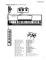
Page 5: ...on 6 PLAY button 7 METRONOME button 8 MASTER VOLUME dial 9 PHONES jacks 0 MIDI IN OUT terminals A PEDAL terminal B Soft pedal left C Sostenuto pedal center D Damper pedal right 1 STANDBY ON スイッチ 2 DEMO SONG ボタン 3 PIANO VOICE ボタン 4 SELECT ボタン 5 REC ボタン 6 PLAY ボタン 7 METRONOME ボタン 8 MASTER VOLUME ダイアル 9 PHONES 端子 0 MIDI IN OUT 端子 A PEDAL 端子 B 左のペダル ソフトペダル C まん中のペダル ソステヌートペダル D 右のペダル ダンパーペダル ...

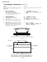
Page 6: ... Close the key cover 2 2 Remove the three 3 screws marked S05 Fig 2 2 3 Slide the top board assembly forward and lift it out 2 屋根Ass y 所要時間 約1分 2 1 スライド蓋を閉じておきます 2 2 S05 のネジ3本を外します 図2 2 3 屋根Ass yを前方へスライドして外します 注意事項 分解のために剥がしたフィラメントテープは 必ず元どおりに貼ってく ださい Caution Be sure to attach the removed filament tape just as it was before removal 3 Back Board Time required About 1 minute Remove the screw marked ...

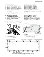
Page 7: ... 4 0X16 MFZN2W3 WE965700 4 3 Speaker R スピーカR S04B Truss Head Tapping Screw 1 TP 1 TRUS 4 0X16 MFZN2W3 WE965700 4 3 5 DJ Circuit Board Time required About 3 minutes 5 1 Remove the top board assembly See procedure 2 5 2 Remove the D JACK assembly See procedure 4 5 3 Remove the three 3 screws marked 3A and the two 2 screws marked 4 The DJ circuit board can then be removed from the D JACK angle Fig 4 ...

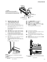
Page 8: ...ime required About 3 minutes each 8 1 Remove the top board assembly See procedure 2 8 2 Remove the key cover assembly See procedure 6 8 3 Remove the three 3 screws marked S09 The rack L can then be removed Fig 6 The left and right rack can then be removed in the same manner 8 ラック L R 所要時間 各約3分 8 1 屋根Ass yを外します 2項参照 8 2 スライド蓋Ass yを外します 6項参照 8 3 S09 のネジ3本を外し ラック L を外します 図6 ラック R も同様に外すことができます Left s...

Page 9: ...1 HP Circuit Board Time required About 6 minutes 11 1 Remove the top board assembly See procedure 2 11 2 Remove the key cover assembly See procedure 6 11 3 Remove the stopper rail assembly See procedure 7 11 4 Remove the rack L See procedure 8 11 5 Remove the end block assembly L See procedure 9 11 6 Remove the two 2 hexagonal nuts marked 3B The HP circuit board can then be removed Fig 7 11 HPシート ...

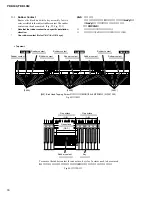
Page 10: ...0X22 MFZN2W3 WF169200 S10 Bind Head Tapping Screw B Bタイト BIND 4 0X10 MFZN2W3 WE974500 3B Hexagonal Nut ナット 特殊 M12X14X2 P 1 0 WF559900 S06 S06 S03D S06 Cable holder 束線固定金具Ass y 3B S10 End block assembly L 拍子木Ass y L S07 S07 S07 S07 End block assembly R 拍子木Ass y R Keyboard assembly GHL GHS 鍵盤Ass y Bottom view 13 4 ラック R を外します 8項参照 13 5 拍子木 R Ass yを外します 9項参照 13 6 30 のネジ2本を外し SWシートを外します 図9 13 4 Remove...

Page 11: ... MFZN2W3 WE970800 S02 Bind Head Tapping Screw 1 TP 1 BIND 3 5X16 MFZN2W3 WE970700 Fig 11 図11 Fig 12 図12 S01 Bind Head Tapping Screw 1 TP 1 BIND 3 5X12 MFZN2W3 WE970900 S02A S02B S02A Back top board assembly 背面框Ass y Front rail assembly 口棒Ass y Arm assembly L 腕木Ass y L S01C S01C S01C S01C S01C S01D S01D S01D S01D S01D S01D S01D Back top board assembly 背面框Ass y Front rail assembly 口棒Ass y Arm assemb...

Page 12: ...he assembly Fig 11 16 8 Remove the fourteen 14 screws marked S01D The front rail assembly can then be removed Fig 12 16 口棒Ass y 所要時間 約12分 16 1 屋根Ass yを外します 2項参照 16 2 スライド蓋Ass yを外します 6項参照 16 3 鍵盤押えAss yを外します 7項参照 16 4 ラック L R を外します 8項参照 16 5 拍子木Ass y L R を外します 9項参照 16 6 GHL GHS 鍵盤Ass yを外します 10項参照 16 7 S02B のネジを左右2本ずつ外します 図11 16 8 S01D のネジ14本を外し 口棒Ass yを外します 図12 PEDAL PK LF cable PK LFケーブル 17 Arm As...

Page 13: ... similar object under the main unit at both sides 20 3 Remove the three 3 screws marked 3C The left stand base can then be removed Fig 17 The right stand base can then be removed in the same manner 20 妻土台 所要時間 約3分 20 1 毛布などの柔かい布を床に敷いて 鍵盤側を上にし て本体を床に置きます 安全のために かならず二人で作業してください 20 2 厚い本 またはそれに類似するもの を側板の下側に 置きます 20 3 3C のネジ3本を外し 妻土台 Lを外します 図17 妻土台 Rも同様にして外します Fig 16 図16 YDP 131 5a Truss Head Screw 小...

Page 14: ...LFケーブルを外します 図13 22 2 ペダルBox Ass yを外します 21項参照 22 3 ペダルAss yを外します 21項参照 22 4 120A のネジ3本を外し アクチュエータ3個を外 します 図19 22 5 120B のネジ1本を外します ソフトペダルを下に押してから 手前に引き出し ます 図19 22 6 130 のネジ1本を外し アース線を外します 図19 22 7 PEDALシートを止めているA部 3箇所 のフレーム の折り曲げを戻します PEDALシートをフレームか ら抜いて 取り出します 図19 22 8 接点ゴムを外します 図19 Bottom view 22 PEDAL Circuit Board Time required About 10 minutes 22 1 Disconnect the PK LF cable Fig 13 22 2 Remov...

Page 15: ... 図20 注 白鍵Ass y 黒鍵Ass yの取り外しの際 グリスが基 板や接点ゴム等に付かないように注意してくださ い 図21 23 4 駆動ラバー 白鍵 黒鍵 の駆動ラバーを外します 図22 23 Disassembling the Keyboard Assembly 23 1 White key assembly and black key assembly Remove the four 4 screws marked 270A fixing the black and white key assembly for one octave C B To remove the back of the black and white key assembly of each octave while pushing the end lug of white keys rearward a...

Page 16: ...します 図23 図23 1 接点ゴムには 向きがあります 接点ゴムは C Cの一連です キーはC B Fig 23 1 図23 1 One octave 1オクターブ C B One octave 1オクターブ C B One octave 1オクターブ C C Rubber contact 接点ゴム Key 鍵盤 To remove the rubber contact for one octave keys for 2 octaves need to be removed 1オクターブ分の接点ゴムを外すのに 2オクターブ分の鍵盤を外します 23 5 Rubber Contact Remove the black and white key assembly for two octaves related to the subject rubber contact The rubber ...

Page 17: ...ole 通し穴 Filament tape フィラメントテープ Top view Side view Fig 24 図24 23 6 GHL88L Circuit Board Remove the black and white key assembly A1 B2 See procedure 23 1 Remove the six 6 screws marked 260A The GHL88L circuit board can then be removed Fig 23 23 7 GHL88M Circuit Board Remove the black and white key assembly C1 B5 See procedure 23 1 Remove the seven 7 screws marked 260B The GHL88M circuit board can t...

Page 18: ...ハンマーを前 に押すと カチッ と音がして鍵盤フレームのハン マー軸からハンマーの軸受け部が外れます ハン マーを横にして取り出します 図25 図26 ハンマーを外すとき ハンマーの軸受け爪や軸受け部を傷 めないように注意して作業してください 23 9 Hammer White Key Black Key Remove the black and white key assembly for the related keys With the key frame placed upside down push the hammer forward from the rear then a click sound is heard and the hammer bearing section can be removed from the hammer axis of the key fra...

Page 19: ...0A to fix the GHL88L circuit boards Fig 23 24 3 GHL88M Circuit Board Connect the FFC cable to CN2 of the GHL88M circuit board attach the filament tape Fig 24 Pass the end of the cable into the through hole in the frame and pull it out from its outlet Fig 24 Tighten the seven 7 screws marked 260B to fix the GHL88M circuit board Fig 23 24 Assembling the Keyboard Assembly 24 1 Hammer White Key Black ...

Page 20: ... クリップ GHL88L Actuate rubber 駆動ラバー Fit in this way はめ込む Apply grease グリス塗布 24 6 Actuate Rubber After applying grease to top and bottom faces of the actuate rubber fit it to the white key black key Fig 30 24 4 GHL88H Circuit Board Tighten the five 5 screws marked 260C to fix the GHL88H circuit board Fig 23 24 5 Rubber Contact Note that the rubber contact has s specific installation direction Be care...

Page 21: ...he white key assembly black key assembly are installed properly Fig 31 Use the four 4 screws marked 270A to fix 1 octave white key assembly black key assembly Fig 20 24 8 Use the two 2 screws marked 270B to fix the A 1 to B 1 keys Fig 20 24 9 Use a screw marked 270C to fix the C7 key Fig 20 LSI PIN DESCRIPTION AK4385ET X6040A00 DAC Digital to Analog Converter 21 YMW767 VTZ X6055A00 CPU SWL01B 22 µ...

Page 22: ...Clock output Port G Ground Power supply 2 5 V Power supply 3 3 V I O port A Ground I O port B 65 66 67 68 69 70 71 72 73 74 75 76 77 78 79 80 81 82 83 84 85 86 87 88 89 90 91 92 93 94 95 96 97 98 99 100 101 102 103 104 105 106 107 108 109 110 111 112 113 114 115 116 117 118 119 120 121 122 123 124 125 126 127 128 Vss IOVDD LBN LWRN PF6 UBN UWRN PF7 RDN PF4 MD00 MD08 MD01 MD09 MD02 MD10 MD03 Vss MD...

Page 23: ...rupt input Port2 Asynchronousserialinterfaceserialdatainput Serialinterfaceserialdatainput Port2 Asynchronousserialinterfaceserialdataoutput Serialinterfaceserialdataoutput Port 2 Asynchronous serial interface serial clock input Serial interface serial clock Port 0 Power supply Ground Port 1 µPD789022GB A15 8E XZ560100 CPU KBS DM IC301 SN74LV32APWR X5647A00 Quad 2 Input OR DM IC106 1 2 3 1A 1Y 4 2...

Page 24: ...X6672C0 28 PN X6672C0 24 SW X6672C0 28 Note See parts list for details of circuit board component parts 注 シートの部品詳細はパーツリストをご参照ください DJ Circuit Board PN Circuit Board MV Circuit Board シート基板図 Component side 部品側 Component side 部品側 Component side 部品側 DJ MV PN 2NA WF20810 2 to DM CN101 PEDAL MIDI OUT IN to DM CN102 DEMO SONG PIANO VOICE SELECT REC PLAY METRONOME MASTER VOLUME to AM CN101 ...

Page 25: ...YDP 131 YDP 131C 25 DM Circuit Board Component side 部品側 Pattern side パターン側 2NA WF20750 to PN CN401 to GHL88M CN2 to AM CN102 to DJ CN101 ...

Page 26: ...YDP 131 YDP 131C 26 AM Circuit Board Component side 部品側 2NA WF20640 3 to MV CN201 to HP CN301 to DM CN401 not installed A A to SPEAKERS to SW CN601 DC IN 12V A A ...

Page 27: ...YDP 131 YDP 131C 27 B B AM Circuit Board 2NA WF20640 3 Pattern side パターン側 B B ...

Page 28: ...C Sostenuto Pedal Soft Pedal C C to DJ JK103 Damper Pedal PEDAL Circuit Board PL Circuit Board HP Circuit Board Component side 部品側 Component side 部品側 Component side 部品側 PHONES to AM CN105 POWER indicator STANDBY ON to AM CN106 SW Circuit Board 1 Component side 部品側 ...

Page 29: ...YDP 131 YDP 131C 29 GHL88L Circuit Board Component side 部品側 D D to GHL88M CN1 D D 2NAK8 WF46230 ...

Page 30: ...YDP 131 YDP 131C 30 GHL88M Circuit Board Component side 部品側 E E to GHL88H CN1 to DM CN301 E E to GHL88L CN1 2NAK8 WF46240 2 ...

Page 31: ...YDP 131 YDP 131C 31 GHL88H Circuit Board Component side 部品側 F F F F to GHL88M CN3 2NAK8 WF46250 ...

Page 32: ...ss the DEMO SONG button 3 To proceed the test Test items are listed in Table 1 Press the corresponding key to select and execute each test See Fig 2 To enter the test item select mode after completing each test item press the DEMO SONG button 4 Test result Each test result is indicated by the sound When the test result is OK the sine wave of C4 sounds When the test result is NG the sine wave of C2...

Page 33: ...heck the ROM checksum connected to the CPU bus Simplified check For the OK test result the sine wave of C4 sounds for 1 second For NG the sine wave of C2 sounds continuously until any key is pressed To check the ROM checksum connected to the CPU bus Simplified check For the OK test result the sine wave of C4 sounds for 1 second For NG the sine wave of C2 sounds continuously until any key is presse...

Page 34: ...the sine wave of 1kHz sounds at the level specified below DAC input full bit 12dB PAN L Connect a level meter with JIS C Filter to the PHONES jack for measurement PHONES L 8 dBu 2dB PHONES R 48dBu or less When the test item is ended with the DEMO SONG button the sound stops This test is executed as a factory test This test is executed as a factory test This test is executed as a factory test Press...

Page 35: ...ds continuously until any key is pressed It takes 11 seconds before checking is completed To check RAM connected to the CPU bus Full address For the OK test result the sine wave of C4 sounds for 1 second For NG the sine wave of C2 sounds continuously until any key is pressed As execution of this test causes the entire data on RAM to be rewritten it is necessary to execute initialization after this...

Page 36: ... METRONOME Order Switch name 1 2 3 4 5 6 Note No C3 D3 E3 F3 G3 A3 LED to light up REC PLAY Table 2 Switch test order No Key Test item Test function and judgment criteria 48 C7 Test Mode Exit To end the test program and reset to the normal mode for restarting ...

Page 37: ...テスト項目の一覧は 表 1 のとおりです 各テストに対応する鍵盤を押すと テストが実行されます 図 2 参照 また 各テスト項目を終了してテスト項目選択状態にする場合 DEMO SONG ボタンを押します 4 テストの結果 テスト結果は 発音で知らせます 結果が OK の場合は C4 のサイン波が発音されます 結果が NG の場合は C2 のサイン波が発音されます C 2 F2 G 2 図1 図2 C0 D0 C 0 D 0 E0 F0 G0 A0 F 0 G 0 A 0 B0 C1 D1 C 1 D 1 E1 F1 G1 A1 F 1 G 1 A 1 B1 C2 D2 C 2 D 2 E2 F2 G2 A2 F 2 G 2 A 2 B2 C3 D3 C 3 D 3 E3 F3 G3 A3 F 3 G 3 A 3 B3 C4 D4 C 4 D 4 E4 F4 G4 A4 F 4 G 4 A...

Page 38: ...査です 簡易チェック OKの場合は C4の正弦波が発音されます 1秒間 発音します NGの場合は C2の正弦波が発音されます NGの場合は何らかの鍵盤を押す まで発音は止まりません CPU のバスに接続されているRAM の結線検査です 簡易チェック OKの場合は C4の正弦波が発音されます 1秒間 発音します NGの場合は C2の正弦波が発音されます NGの場合は何らかの鍵盤を押す まで発音は止まりません Flash ROMの特定のバンクに対する消去 書き込み 読み出しの検査です 簡易チェック OKの場合は C4の正弦波が発音されます 1秒間 発音します NGの場合は C2の正弦波が発音されます NGの場合は何らかの鍵盤を押す まで発音は止まりません チェック完了まで6秒かかります 2 3 4 5 C 3 D3 D 3 E3 Master ROM チェック 1 Slave ROM チェック...

Page 39: ...ベル DAC入力フルビット 12dB で発音され ることを確認します PAN L PHONES 端子にレベルメーター JIS C フィルター使用 を接続して測定し ます PHONES L 8 dBu 2 dB PHONES R 48 dBu 以下 DEMO SONG ボタンでテスト項目を終了する際 発音が止まります 工場検査用のテストです 工場検査用のテストです 工場検査用のテストです 表2 P 41 の順番に各スイッチを2個押ししないように押して行きます 各ス イッチを押した時 そのスイッチに対応する音程で P 41 の表2参照 正弦波 が発音されます また スイッチに対応するLEDがある場合は スイッチが 押されている間LEDが点灯します すべてのスイッチが正しく押され OKとなることを確認します 指定外のスイッチが押された場合はNGとなります スイッチを実際には押しているが 押された...

Page 40: ...まで発音は止まりません 工場検査用のテストです CPU のバスに接続されているROMのチェックサム検査です フルアドレス OKの場合は C4の正弦波が発音されます 1秒間 発音します NGの場合は C2の正弦波が発音されます NGの場合は何らかの鍵盤を押す まで発音は止まりません チェック完了まで10秒かかります CPU のバスに接続されているROMのチェックサム検査です フルアドレス OKの場合は C4の正弦波が発音されます 1秒間 発音します NGの場合は C2の正弦波が発音されます NGの場合は何らかの鍵盤を押す まで発音は止まりません チェック完了まで11秒かかります CPU のバスに接続されているRAMの検査です フルアドレス OKの場合は C4の正弦波が発音されます 1秒間 発音します NGの場合は C2の正弦波が発音されます NGの場合は何らかの鍵盤を押す まで発音は止まりま...

Page 41: ... C5 C7 Factory Set Test Mode Exit 全てのバックアップ領域を初期化して 工場出荷状態にします RAMおよび Flash 全データが消去されるので 注意してください OKの場合は C4の正弦波が発音されます 1秒間 発音します NGの場合は C2の正弦波が発音されます NGの場合は何らかの鍵盤を押す まで発音は止まりません ここでは初期化用のフラグを立てるだけで 実行は次回電源起動時に行われ ます このFactory Setを実行した後 必ずテストNo 48の Test Exit を実施してくだ さい 再起動 RE BOOT した時に実際のメモリーの初期化が行われます 再起動後 は LEDの点滅が終わるまで電源を切らないでください 完了まで5秒かかります テストプログラムを終了し 通常モードに戻ります 再起動します ...

Page 42: ...ed in flash memory on this instrument This data will be kept after you turn off the power to the instrument Initializing the settings When you initialize the settings all data excluding the user song and songs loaded from a computer will be initialized and reset to the factory default settings While holding down the C7 the highest key turn on the power to the instrument The data excluding the data ...

Page 43: ... ユーザーソングとコンピューターから読み込んだソング以外の データが初期化 工場出荷時の状態になります されます 初期化実行中 REC レ コード と PLAY プレイ のランプ点滅中 は電源を切らない でください この楽器 が 何らかの原因で操作不 能になったり 誤動作した場合は 一旦電源を切り 初期化を行なって ください 右端の鍵盤 C7 を押しながら電源を入れます 自分で録音したソング コンピューターから読み込んだソング以外の データが初期化されます バックアップデータ メトロノームの音量 メトロノームの拍子 タッチ感度 チューニング 自分で録音したソング ユーザーソング データ コンピューターから読み込んだソングデータ 右端の鍵盤 C7 ...

Page 44: ...g Data Between the Computer and Instrument for unprotected data in the Help file that came with Musicsoft Downloader Requirements for song data that can be loaded from a computer to this instrument Number of songs Up to 10 songs plus one user song Maximum data size Total 352 KB Data format SMF Format 0 and YDP 131 BUP user song Transmitting Song Data from the Digital Piano to a Computer Musicsoft ...

Page 45: ...場合は データどおりに再生できません コンピューターからソングデータを楽器に読み込む方法は ミュージックソフトダウンロー ダーについているヘルプ コンピューターと電子楽器の間でデータを転送する をご参照く ださい コンピューターから楽器に読み込める内容 ソング 最大10ソング ユーザーソング データ量 合計で352KB キロバイト データフォーマット SMFFormat0 とYDP 131 BUP ユーザーソング 楽器からソングデータをコンピューターに送信する ミュージックソフトダウンローダーを使って 楽器内のユーザーソングをコンピューター に送信できます ユーザーファイルをコンピューターに送信する方法は ミュージックソフトダウンローダー についているヘルプ コンピューターと電子楽器の間でデータを転送する をご参照くださ い 楽器からコンピューターへ送信できる内容 ユーザーソング YDP ...

Page 46: ...tive Sense Reset Notes 1 1 16 1 16 3 x 1 16 0 127 o 9nH v 1 127 x x 1 x x 1 o o o o x 1 x 1 x 1 o 0 127 o 0 127 o x x x o o x o o o o x o o o o o x 3 x x 0 127 0 127 o 9nH v 1 127 x x x o 0 24 semi o o o o o o o o o o o o x x x o o 123 125 122 121 120 126 127 Bank Select Modulation Main Volume Panpot Expression Data Entry Portament Control Effect Depth RPN Inc Dec RPN LSB MSB These Control Change ...

Page 47: ...hat are controllable with RPN Coarse Tune Fine Tune Pitch Bend Range 3 MODE MESSAGES Data format BnH cc vv BnH Control event n channel number cc Control number vv Data Range 1 All Sound Off ccH Parameter Data Range vvH 78H All Sound Off 00H 2 Reset All Controllers ccH Parameter Data Range vvH 79H Reset All Controllers 00H Resets controllers as follows Controller Value Expression 127 max Damper Ped...

Page 48: ...e XnH When n is received n 0 F whichever is received X don t care 04H Sub ID 1 Device Control Message 01H Sub ID 2 Master Volume llH Volume LSB mmH Volume MSB F7H End of Exclusive 2 Universal Non Realtime Message GM On General MIDI Mode On Data format F0H 7EH XnH 09H 01H F7H F0H Exclusive status 7EH Universal Non Realtime 7FH ID of target device 09H Sub ID 1 General MIDI Message 01H Sub ID 2 Gener...

Page 49: ... Note that the table s Total Size value gives the size of a bulk block Only the top address of the block 00H 00H 00H is valid as a bulk data address 9 SYSTEM EXCLUSIVE MESSAGES Digital Piano MIDI Format Data format F0H 43H 73H xxH nnH F7H F0H Exclusive status 43H Yamaha ID 73H Digital Piano ID 01H Product ID digital piano common xxH Substatus nn Control 02H Internal MIDI clock 03H External MIDI cl...

Page 50: ...t MIDI Map for a complete list of Reverb Chorus and Variation type numbers Address H Size H Data H Parameter Description Default value H 02 01 00 2 00 7F REVERB TYPE MSB Refer to Effect MIDI Map 01 HALL1 00 7F REVERB TYPE LSB 00 basic type 00 02 01 40 2 00 7F VARIATION TYPE MSB Refer to Effect MIDI Map 00 Effect off 00 7F VARIATION TYPE LSB 00 basic type 00 VARIATION refers to the EFFECT on the pa...

Page 51: ...inally installed Notes DESTINATION ABBREVIATIONS The numbers QTY show quantities for each unit The parts with in PART NO are not available as spare parts This mark in the REMARKS column means these parts are interchangeable The second letter of the shaded part number is O not zero The second letter of the shaded part number is I not one M South African model O Chinese model Q South east Asia model...

Page 52: ... 16 5c 5e 4 x 12 5b 2 5d 5c 5c 5a 5a 5b 5b AC Adaptor ACアダプター Main Unit See page 4 メ イ ンユニッ ト Side Board Assembly R See page 18 側板Ass y R Side Board Assembly L See page 18 側板Ass y L Pedal Box Assembly See page 20 ペダルBox Ass y 5ea Cord Clamp Set 22 24 25 OVERALL ASSEMBLY 総組立 ...

Page 53: ...el CCC O WE64010 ACCESSORIES Z AC Adaptor PA 5D J J Z AC Adaptor PA 5D U YDP 131C U 08 Z AC Adaptor PA 5D E E 08 Z AC Adaptor PA 5D GBR B 09 Z AC Adaptor PA 5D CHN O 08 Bench BC 104DR YDP 131 J N O Bench BC 104CH YDP 131C J N O Bench BC 104CH YDP 131C U Headphone P402522A0000 05971 J 07 TOOL Rod 99 WF072400 WF072600 WF072500 WF072700 WF508600 WF508700 WF001300 WA015500 WE997700 WE969400 WE998900 V...

Page 54: ...9 S02 S02 Rear view Top view 1 Top view 2 Side view 1 Side view 2 Side view 3 D JACK Assembly See page 17 Dジ ャ ッ クAss y Key Cover Assembly See page 16 スライ ド蓋Ass y Top Board Assembly See page 14 屋根Ass y 17 Music Rest Assembly See page 15 譜面板Ass y 20a 20b 20 32 MAIN UNIT メインユニット ...

Page 55: ...k Assembly R See page 13 拍子木 R Ass y End Block Assembly L See page 12 拍子木 L Ass y Arm Assembly L See page 10 腕木Ass y L Arm Assembly R See page 10 腕木Ass y R Back Top Board Assembly See page 9 背面框Ass y Keybed Assembly See page 7 棚板集成 Headphones Jack Assembly See page 24 HPジ ャ ッ クAss y Front Rail Assembly See page 8 口棒Ass y Keyboard Assembly See page 22 GHL鍵盤束線付B 21 22 32 ...

Page 56: ...d Head Tapping Screw 1 3 5X16 MFZN2W3 10 01 S03 Bind Head Tapping Screw B 3 0X8 MFZN2W3 19 01 S04 Truss Head Tapping Screw 1 4 0X16 MFZN2W3 8 01 S05 Truss Head Screw 4 0X16 MFZN2B3 3 01 S06 Bind Head Screw 4 0X18 MFZN2W3 PO 9 01 S07 Bind Head Tapping Screw P 4 0X22 MFZN2W3 PO 8 01 S08 Guide Screw 6 0X20 3 14 2 02 S09 Bind Head Tapping Screw 1 3 5X20 MFZN2W3 6 01 S10 Bind Head Tapping Screw B 4 0X1...

Page 57: ... Keybed Assembly WF05530 1a Nut B 4 0X11 5 MFZN2W3 9 01 1b Nut 6 0X12 5 B 6 01 3 Cushion PEFU2X4X330TE PUTS V890430 2 4 Speaker Grille WF53790 2 WF055200 WF624100 WF582400 棚 板 集 成 棚 板 集 成 棚 板 木 部 集 成 鬼 目 ナ ッ ト ナ ッ ト オ ニ メ ク ッ シ ョ ン S P グ リ ル 塗 装 品 New Parts RANK Japan only REF NO PART NO DESCRIPTION REMARKS QTY RANK 部 品 名 ...

Page 58: ...ont Rail Sub Assembly YDP 131C 05 1a Holder Rail 1 6 L 2 1b L Angle WF07000 7 1c Bind Head Tapping Screw 1 3 5X10 MFZN2W3 18 01 4 Circuit Board PL 05 6 Bind Head Tapping Screw 1 3 5X10 MFZN2W3 01 WF723900 WF724000 WH173900 WE970800 WF208700 WE970800 口 棒 A s s y 口 棒 A s s y 口 棒 A s s y 口 棒 サ ブ A s s y 口 棒 サ ブ A s s y ア ン グ ル K L ア ン グ ル T P 1 B I N D P L シ ー ト T P 1 B I N D New Parts RANK Japan onl...

Page 59: ...Back Top Panel RIGHT WF07060 4 L Angle WF07000 5 5 Bind Head Tapping Screw 1 3 5X10 MFZN2W3 16 01 6 Cord Holder L 80 8 03 8 Felt 25X25X1 N5000NS V591600 4 WF057600 WE970800 VU891300 背 面 框 A s s y 背 面 框 A s s y 背 面 框 背 面 框 ア ン グ ル L 背 面 框 ア ン グ ル R L ア ン グ ル T P 1 B I N D ビ ニ タ イ 黒 1 0 芯 L フ ェ ル ト New Parts RANK Japan only REF NO PART NO DESCRIPTION REMARKS QTY RANK 部 品 名 BACK TOP BOARD ASSEMBLY 背面...

Page 60: ... YDP 131C 10 1 2 10 9 9 4 5 8 7 8 8 6 Top view Side view Rear view Front view 12 Arm Assembly L only 腕木Ass y L のみ ARM ASSEMBLY 腕木 Ass y NOTE This figure shows the left arm assembly 注 このイラストは腕木 Ass y L を表わしています ...

Page 61: ...L LEFT YDP 131 YDP 131C Arm Assembly L LEFT YDP 131 11 Arm Assembly L LEFT YDP 131C 11 1 Side Cover L LEFT YDP 131 WF05840 1 Side Cover L LEFT YDP 131C WF06940 2 Guide Rail L LEFT YDP 131 03 2 Guide Rail L LEFT YDP 131C 02 4 Felt 60X12 V257700 5 Holder Top Board L MFZN2BL V752270 6 Angle Bracket 03 7 L Angle WF07000 2 8 Bind Head Tapping Screw 1 3 5X16 MFZN2W3 8 01 9 Bind Head Tapping Screw 1 3 5X...

Page 62: ...6 Button Green B LENS PLAY 01 7 Button Red B LENS REC 01 8 Volume Knob MASTER VOLUME 04 9 Bind Head Tapping Screw B 3 0X8 MFZN2W3 9 01 11 Cable Assembly PANEL WF87060 11a Connector Assembly VR PH 9P L 1070 WF21570 11b Connector Assembly PN PH 9P L 880 WF21580 12 Cord Holder BK 1 01 13 Nonwoven Fabric Cloth V926650 6 14 Nonwoven Fabric Cloth WG79930 6 WF101600 WF154700 WF208300 WF208400 V8065100 V8...

Page 63: ...IGHT YDP 131 02 10 End Block Sub Assembly R RIGHT YDP 131C 02 10a Nonwoven Fabric Cloth 25X8X0 35 V468640 20 Angle PL WE90570 30 Bind Head Tapping Screw B 3 0X8 MFZN2W3 3 01 40 Push Knob Black STANDBY ON 02 60 Circuit Board SW 05 WF088700 WF154000 WE774300 VF663400 WF208600 拍子木 R Ass y 拍子木 R Ass y 拍子木 R Ass y 拍子木RサブAss y 拍子木RサブAss y 不 織 布 ア ン グ ル P L B タ イ ト B I N D プ ッ シ ュ ツ マ ミ S W シ ー ト New Par...

Page 64: ...re YDP 131 05 2 Stopper Rail Music Score YDP 131C 13 3 Screw 2 2X5 8 MFZN2W3 4 01 4 Holder Top Board FRONT 2 03 5 Holder Top Board REAR 3 05 6 Bind Head Tapping Screw 1 4 0X14 MFZN2W3 10 01 7 Felt 1290X16X1 0 WG42240 WF058600 WF058700 V2780400 WF425200 WF054600 VQ485700 VQ485800 WE971900 屋 根 A s s y 屋 根 A s s y 屋 根 A s s y 屋 根 屋 根 譜面止レールAss y 譜面止レールAss y 特 注 ネ ジ 屋 根 固 定 金 具 F 屋 根 固 定 金 具 R T P 1 B...

Page 65: ...YDP 131C 08 1 Music Rest YDP 131 WF11420 1 Music Rest YDP 131C WF11430 2 Hinge 2 05 3 Cap 2 03 4 Bind Head Tapping Screw 1 3 0X10 MFZN2B3 4 01 WF069600 WF069700 V8437600 VV965900 WF109400 譜 面 板 A s s y 譜 面 板 A s s y 譜 面 板 A s s y 譜 面 板 印 刷 品 譜 面 板 印 刷 品 譜 面 蝶 番 蝶 番 キ ャ ッ プ T P 1 B I N D New Parts RANK Japan only REF NO PART NO DESCRIPTION REMARKS QTY RANK 部 品 名 ...

Page 66: ...sive Tape 500 W 12 VE36310 4 Cushion 6X2 5XT4 3 01 6 Holder Assembly R RIGHT 3 6a Holder Rod R RIGHT 3 03 6b Bushing 3 03 7 Bind Head Tapping Screw 1 3 5X8 MFZN2W3 13 8 Rod 9 Gear M90S 2 01 10 Bind Head Screw 3 0X10 MFZN2W3 2 01 WF071800 WF071900 WF223400 WF439500 WF875600 V9465400 V8901500 VV285700 VS368500 WF745300 V8517000 V9857900 WE952900 ス ラ イ ド 蓋 A s s y ス ラ イ ド 蓋 A s s y ス ラ イ ド 蓋 A s s y ...

Page 67: ...CK WE91690 2 Circuit Board DJ 11 3 Bind Head Tapping Screw B 3 0X8 MFZN2W3 3 01 4 Bind Head Tapping Screw B 3 0X8 MFZN2W3 2 01 WF208200 WE774300 WE774300 D ジ ャ ッ ク A s s y D ジ ャ ッ ク A s s y D ジ ャ ッ ク 金 具 印 刷 品 D J シ ー ト B タ イ ト B I N D B タ イ ト B I N D New Parts RANK Japan only REF NO PART NO DESCRIPTION REMARKS QTY RANK 部 品 名 ...

Page 68: ...YDP 131 YDP 131C 18 5 6 7 1 8 2 3 9 9 9 3 3 Top view Bottom view Front view Side view NOTE This figure shows the left side board assembly 注 このイラストは側板 Ass y L を表わしています SIDE BOARD ASSEMBLY 側板 Ass y ...

Page 69: ... N D SIDE BOARD ASSEMLBY L LEFT YDP 131 YDP 131C Side Board Assembly L LEFT YDP 131 08 Side Board Assembly L LEFT YDP 131C 08 1 Side Board L LEFT YDP 131 WF07280 1 Side Board L LEFT YDP 131C WF07300 2 Stand Base YDP 131 06 2 Stand Base YDP 131C 05 3 Pan Head Tapping Screw 1 4 0X65 MFZN2W3 3 01 5 Holder Back Board 34 05 6 Holder Stand LEFT 05 7 Angle Bracket ST 24 04 8 Holder PB 02 9 Bind Head Tapp...

Page 70: ...embly T 25 3 Nylon Clamp NK 3N 01 4 Caution Label Clavinova 03 5 Bind Head Tapping Screw 1 4 0X14 MFZN2W3 8 01 6 Truss Head Tapping Screw 1 4 0X14 MFZN2W3 01 WF073400 WF073500 WF224300 CB065520 VD966100 WE971900 WE965100 ペダルBoxAss y ペダルBoxAss y ペダルBoxAss y ペ ダ ル B O X ペ ダ ル B O X ペ ダ ル A s s y T ナ イ ロ ン ク ラ ン プ ペ ダ ル 注 意 書 T P 1 B I N D T P 1 T R U S New Parts RANK Japan only REF NO PART NO DESCRI...

Page 71: ...ber Contact PEDAL 3 03 110 Circuit Board PEDAL 05 120 Bind Head Tapping Screw B 3 0X8 MFZN2B3 10 01 130 Screw 40XM6X46 MFZN2B3 140 Grease G 31KA 50g VE96850 10 240 Cord Holder BK 1 2 01 WF224300 VU339700 WC970100 WC507400 WC507600 VV433500 VP348100 VU346500 VU339800 V0044700 VU456000 WB970200 WE774400 WF054500 TX920280 CB069250 ペ ダ ル A s s y T ペ ダ ル A s s y T ペ ダ ル フ レ ー ム ペ ダ ル 本 体 C ペ ダ ル 本 体 L ...

Page 72: ...30d 230b 230a 260 270 270 270 270 20a 20b 20b 30a 70a 70a 30a 30 70 20 20 30 60 70 20a 80a 80 80b 40a 40 50 50a 50b 40b 30b 30b 70b 70b 60b 60a 260 260 210 200 200 200 200 200 200 200 280 10 120 160 GHL88 Circuit Board Assembly GHL88シー ト 1 Keyboard Assembly GHL鍵盤Ass y 4 2 3 KEYBOARD ASSEMBLY GHL 鍵盤束線付B ...

Page 73: ...190 Limit Stopper 88 WF21190 2 200 Rubber Contact OCT C 0 C1 C 1 C2 C 2 C3 7 04 C 3 C4 C 4 C5 C 5 C6 C 6 C7 210 Rubber Contact A C A 1 C0 05 230 GHL88 Circuit Board Assembly WG31750 230a Circuit Board GHL88L 13 230b Circuit Board GHL88M 13 230c Circuit Board GHL88H 12 230d Connector Assembly 17P WF21290 2 260 Bind Head Tapping Screw P 2 6X8 MFZN2W3 18 01 270 Bind Head Tapping Screw P 3 0X16 MFZN2W...

Page 74: ...phones Jack Assembly WF22310 1 Circuit Board HP 05 2 Angle Headphone 04 3 Hexagonal Nut M12X14X2 P 1 0 2 01 WF208500 VN631800 WF559900 HPジャックAss y HPジャックAss y H P シ ー ト H P 取 付 金 具 ナ ッ ト 特 殊 New Parts RANK Japan only REF NO PART NO DESCRIPTION REMARKS QTY RANK 部 品 名 HEADPHONES JACK ASSEMBLY HPジャック Ass y ...

Page 75: ...N O Bench BC 104CH YDP 131C U 1 Hexagonal Head Bolt M10X50mm 4 2 Spring Washer 10X3mm 4 01 ACCESSORY Wrench DR 01 02 WH499000 WH499200 WH499300 AAX74480 WF577600 同 梱 品 セ ッ ト 椅 子 同 梱 品 セ ッ ト 椅 子 同 梱 品 セ ッ ト 椅 子 同 梱 品 セ ッ ト 椅 子 六 角 ボ ル ト バ ネ 座 金 付 属 品 ベ ン チ ス パ ナ New Parts RANK Japan only REF NO PART NO DESCRIPTION REMARKS QTY RANK 部 品 名 ...

Page 76: ...or ECQ V1H224JL3 01 C205 Monolithic Mylar Capacitor ECQ V1H154JL3 01 C206 Mylar Capacitor 0 0680 50V J RX TP 02 C207 Ceramic Capacitor B 470P 50V K RX TP 01 C207 Ceramic Capacitor 2B 470P 63V K FORMING C208 Electrolytic Cap 10 00 50 0V RX TP 01 C209 Mylar Capacitor 1000P 50V J RX TP 01 C210 Monolithic Ceramic Cap 1 000 25V Z 01 C211 Mylar Capacitor 470P 50V J RX TP 01 C212 Mylar Capacitor 0 1000 5...

Page 77: ...P 0 1W 0 1W 04 IC401 IC BA50BC0T REGULATOR 5V 03 IC402 IC BA50BC0T REGULATOR 5V 03 J301 Jumper Wire 0 55 VA07890 Z JK401 Connector HTJ 020 05AZ DC IN 12V 04 Z L401 Line Filter CM08RB01 RX 03 MF401 Holder DC JACK WF07020 R101 Carbon Resistor chip 1 0K 63M J RECT 01 R102 Carbon Resistor chip 33 0K 63M J RECT 01 R103 Carbon Resistor chip 47 0K 63M J RECT 01 R104 Carbon Resistor chip 3 3K 63M J RECT 0...

Page 78: ...rd SW WF20810 X6672C0 05 Jumper Wire 0 55 VA07890 C101 Ceramic Capacitor F 0 0100 50V Z RX TP 01 C101 Ceramic Capacitor 2F 0 01 63V Z FORMING C103 Ceramic Capacitor F 0 0100 50V Z RX TP 01 C103 Ceramic Capacitor 2F 0 01 63V Z FORMING C104 Electrolytic Cap 22 00 10 0V RX TP 01 C105 Ceramic Cap B 100P 50V K RX TP 01 108 Ceramic Cap B 100P 50V K RX TP 01 C301 Ceramic Capacitor B 1000P 50V K RX TP 01 ...

Page 79: ... 01 SW405 Tact Switch SKQNAJ PLAY 01 SW405 Tact Switch SKRGAMD010 01 SW405 Push Switch EVQ 11Y 07K 01 SW406 Tact Switch SKQNAJ METRONOME 01 SW406 Tact Switch SKRGAMD010 01 SW406 Push Switch EVQ 11Y 07K 01 Z SW601 Push Switch SDDLB1 B2 J UC CE STANDBY ON 03 TR101 Transistor 2SC1740S R S 01 TR101 Transistor 2SC5395 T112 E F G TR101 Transistor KTC3199 GR BL TR102 Transistor 2SC1740S R S 01 TR102 Tran...

Page 80: ...C305 Ceramic Capacitor CH chip 22P 50V J RECT 01 C306 Ceramic Capacitor CH chip 22P 50V J RECT 01 C307 Ceramic Capacitor SL chip 100P 50V J RECT 01 333 Ceramic Capacitor SL chip 100P 50V J RECT 01 C334 Ceramic Capacitor F chip 0 1000 25V Z RECT 01 C401 Electrolytic Cap chip 10 16V 01 C402 Ceramic Capacitor F chip 0 1000 25V Z RECT 01 C403 Ceramic Capacitor F chip 0 1000 25V Z RECT 01 C405 Ceramic ...

Page 81: ...CT 01 R134 Carbon Resistor chip 47 0 63M J RECT 01 R135 Carbon Resistor chip 47 0K 63M J RECT 01 R136 Carbon Resistor chip 47 0 63M J RECT 01 R137 Carbon Resistor chip 47 0K 63M J RECT 01 140 Carbon Resistor chip 47 0K 63M J RECT 01 R144 Carbon Resistor chip 2 2K 63M J RECT 01 149 Carbon Resistor chip 2 2K 63M J RECT 01 R150 Carbon Resistor chip 47 0K 63M J RECT 01 155 Carbon Resistor chip 47 0K 6...

Page 82: ...2151 17P SE 01 D1 Diode 1SS133 1SS176 01 48 Diode 1SS133 1SS176 01 Circuit Board GHL88L WF46230 X6244D0 13 CN1 Wire Trap 52151 17P SE 01 D1 Diode 1SS133 1SS176 01 D5 Diode 1SS133 1SS176 01 60 Diode 1SS133 1SS176 01 Circuit Board GHL88M WF46240 X6245G0 13 CN1 Wire Trap 52151 17P SE 01 CN2 FFC Connector 52807SHIRI ZU 27P CN3 Wire Trap 52151 17P SE 01 D1 Diode 1SS133 1SS176 01 72 Diode 1SS133 1SS176 ...

Page 83: ...3D CN101 10P 10P 9P CN101 3 3D 3 3D DAMP SOSTE SOFT IC101 6P SOFT SOSTENUTO DAMPER MIDI ICN MIDIRX MIDITX 3 3D Photo Coupler SWL01 T MASTER CPU IC101 128P SWL01 T SLAVE CPU IC201 128P CPU KBS POWER AMP 6W 6W POWER AMP 0 1W 0 1W IC301 44P MIDI OUT PEDAL IN PEDAL 3 3D 3 3D CN301 CN101 5D DGND DGND 27P LED DRIVER TR101 5 2 57 58 18 23 PROGRAM WAVE 64Mbit PROGRAM WAVE 32Mbit IC102 48P IC202 48P FLASH ...

Page 84: ...BS AND AND FLASH ROM 64M PROG WAVE FLASH ROM 32M PROG WAVE REGULATOR 3 3V DAC OP AMP REGULATOR 2 5V FLASH ROM 4M DRAM 4M OR Not installed 未実装 Ceramic Capacitor セラミックコンデンサー Note See parts list for details of circuit board component parts 注 シートの部品詳細はパーツリストをご参照ください RH5RZ25CA T1 F X3679A00 REGULATOR 2 5V DM IC404 1N4148 VV437800 DIODE DJ D101 107 BA33BC0FP X5889A00 REGULATOR 3 3V DM IC403 DJ PN not in...

Page 85: ...DM CN401 to DM CN301 WARNING Components having special characteristics are marked Z and must be replaced with parts having specification equal to those originally installed Note See parts list for details of circuit board component parts BA50BC0T X5887A00 REGULATOR 5V AM IC401 402 2A02GM V8603100 2A02M VV731400 DIODE AM D401 Not installed 未実装 Ceramic Capacitor セラミックコンデンサー Mylar Capacitor マイラーコンデンサ...

Reviews: