YDP-131/YDP-131C
13
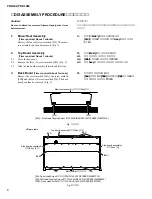
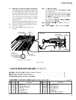
Fig. 15
(図15)
19.
Side Board Assemble (L, R)
(Time required: About 4 minutes)
19-1
Disconnect the PK-LF cable. (Fig. 13)
19-2
Remove the main unit. (See procedure 18)
19-3
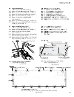
Remove the screw marked [5bA] and the two (2)
screws marked [5a]. The side board assembly L can
then be removed. (Fig. 2, 16)
*
The side board assembly R can then be removed in
the same manner.
19.
側板Ass y
(L・R)
(所要時間:約4分)
19-1
PK-LFケーブルを外します。
(図13)
19-2
メインユニットを外します。
(18項参照)
19-3
[5bA]のネジ1本と[5a]のネジ2本を外し、
側板Ass y
(L)
を外します。
(図2、
16)
※
側板Ass y (R) も同様に外すことができます。
20.
Stand Base
(Time required: About 3 minutes)
20-1
With a soft cloth like a blanket placed on the floor,
place the main unit on its back board gently.
*
For safety, this work should be done by two persons.
20-2
Put thick books or similar object under the main unit
at both sides.
20-3
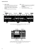
Remove the three (3) screws marked [3C]. The left
stand base can then be removed. (Fig. 17)
*
The right stand base can then be removed in the same
manner.
20.
妻土台
(所要時間:約3分)
20-1
毛布などの柔かい布を床に敷いて、
鍵盤側を上にし
て本体を床に置きます。
※
安全のために、かならず二人で作業してください。
20-2
厚い本
(またはそれに類似するもの)
を側板の下側に
置きます。
20-3
[3C]のネジ3本を外し、
妻土台 Lを外します。
(図17)
※
妻土台 Rも同様にして外します。
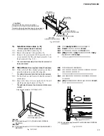
Fig. 16
(図16)
YDP-131
[5a]: Truss Head Screw (小ネジ+TRUS) 6.0X20 MFZN2B3
(WF001300)
YDP-131C
[5a]: Truss Head Screw (+トラス小ネジ) 6.0X20 BROWN MFC2
(WA015500)
Fig. 17
(図17)
[3C]: Pan Head Tapping Screw-1
(TP#1+PAN)
4.0X65 MFZN2W3
(WF514200)
[5a]
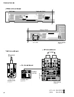
Side board assembly L
(側板Ass'y L)
Pedal box assembly
(ペダルBox Ass'y)
[3C]
Stand base
(妻土台)
Hold here.
(ここを持ってください。)
Do not hold here.
(ここを持たないでください。)
Z
CAUTION
Do not hold the key cover or top portion.
(キーカバーや屋根板を持たないでください。)
For safety, this work should be done by two persons.
(安全のために、
かならず二人で作業してください。)
Do not hold here.
(ここを持たないでください。)
Key cover
(キーカバー)
Top portion
(屋根板)


