Fig. 4
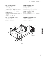
2-5. Removal of MAIN P.C.B. (Fig. 4)
a.
Remove 6 screws (
⑥
).
b.
Remove CN100 and CON2.
c.
Remove the MAIN P.C.B.
2-6. Removal of Power Supply Unit (Fig. 4)
a.
Remove 4 screws (
⑦
).
b.
Remove the solder of the L/N connector and
disconnect 2 cables.
c.
Remove the power supply unit.
2-5. MAIN P.C.B. の外し方(Fig. 4)
a.
⑥ のネジ 6 本を外します。
b.
CN100、CON2 を外します。
c.
MAIN P.C.B. を外します。
2-6. 電源ユニットの外し方(Fig. 4)
a.
⑦ のネジ 4 本を外します。
b.
L/N 端子の半田を取り除き、ケーブル 2 本を外し
ます。
c.
電源ユニットを外します。
Rubber sheet and the cloth
ゴムシートと布
MAIN P.C.B.
Bottom cabinet assembly
ボトムキャビネット Ass'y
CON2
CN100
⑦
Power supply unit
電源ユニット
L/N
⑥
⑥
20
YAS-CU207/ATS-CU2070/NS-WSW42
Y
A
S-CU207/A
TS-CU2070/
NS-WSW42


