background image


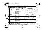
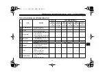
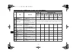
PERIODIC MAINTENANCE AND ADJUSTMENT


7-16


2

3

4

5

6

7

8

9


EAU45154


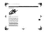
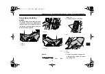
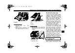
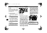
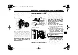
To change the coolant


1. Place the vehicle on a level sur-

face and let the engine cool if nec-
essary.

2. Remove panels A and C. (See

page 7-8.)

3. Place a container under the engine

to collect the used coolant.

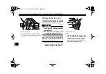
4. Remove the radiator cap retaining

bolt and radiator cap. 


WARNING!

Never attempt to remove the ra-
diator cap when the engine is
hot.


[EWA10381]


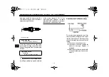
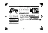
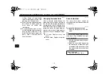
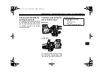
5. Remove the coolant reservoir by

removing the bolts.

6. Remove the coolant reservoir cap.

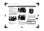
7. Drain the coolant from the coolant

reservoir by turning it upside down.

8. Install the coolant reservoir by

placing it in the original position,
and then installing the bolts.

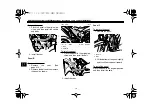
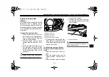
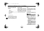
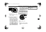
9. Remove the coolant drain bolt to

drain the cooling system.

10. After the coolant is completely

drained, thoroughly flush the cool-
ing system with clean tap water.

11. Install the coolant drain bolt, and

then tighten it to the specified
torque.

TIP


Check the washer for damage and re-


place it if necessary.

12. Pour the specified amount of the


1. Radiator cap
2. Radiator cap retaining bolt

2

1


1. Bolt

1. Coolant reservoir cap

1

1


1. Coolant drain bolt


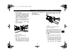
Tightening torque:


Coolant drain bolt:

10 Nm (1.0 m·kgf, 7.2 ft·lbf)

1

Summary of Contents for WR25R 2008

Page 1: ...32C 28199 12 WR25RY C OWNER S MANUAL Read this manual carefully before operating this vehicle LIT 11626 22 62...

Page 2: ...EAU10042 Read this manual carefully before operating this vehicle This manual should stay with this vehicle if it is sold Q...

Page 3: ...of the motorcycle To maintain these high standards it is important that you and your Yamaha dealer pay close attention to the recommended maintenance schedules and operating instructions contained wi...

Page 4: ...ersonal injury hazards Obey all safety messages that follow this symbol to avoid possible injury or death A WARNING indicates a hazardous situation which if not avoided could result in death or seriou...

Page 5: ...S MANUAL 2008 by Yamaha Motor Corporation U S A 1st edition June 2008 All rights reserved Any reprinting or unauthorized use without the written permission of Yamaha Motor Corporation U S A is expres...

Page 6: ...l maintenance and lubrication chart 7 4 Removing and installing panels 7 8 Checking the spark plug 7 10 Canister for California only 7 11 Engine oil and oil filter element 7 12 Coolant 7 15 Cleaning t...

Page 7: ...7 39 Rear wheel 7 40 Troubleshooting 7 41 Troubleshooting charts 7 43 MOTORCYCLE CARE AND STORAGE 8 1 Matte color caution 8 1 Care 8 1 Storage 8 3 SPECIFICATIONS 9 1 CONSUMER INFORMATION 10 1 Identif...

Page 8: ...f the labels on your vehicle They contain important information for safe and proper operation of your vehicle Never remove any labels from your vehicle If a label becomes difficult to read or comes of...

Page 9: ...ction and protective clothing 5GK 2118K 00 2 32D 21668 01 Cold tire normal pressure should be set as follows Up to 90 kg 198 lbs load 125 kPa 1 25 kgf cm2 18 psi 175 kPa 1 75 kgf cm2 25 psi 90 kg 198...

Page 10: ...LOCATION OF IMPORTANT LABELS 1 3 1 2 3 4 5 6 7 8 9 1...

Page 11: ...LOCATION OF IMPORTANT LABELS 1 4 1 2 3 4 5 6 7 8 9 1...

Page 12: ...recognize motorcycles in traf fic is the predominating cause of automobile motorcycle accidents Many accidents have been caused by an automobile driver who did not see the motorcycle Making yourself...

Page 13: ...oose fitting clothes otherwise they could catch on the control levers footrests or wheels and cause injury or an accident Always wear protective clothing that covers your legs ankles and feet The engi...

Page 14: ...cessory mounts and cargo restraints frequently Properly adjust the suspension for your load and check the con dition and pressure of your tires Never attach any large or heavy items to the handlebar f...

Page 15: ...t be as lightweight as possible and should be kept to a minimum Bulky or large accessories may seriously affect the stability of the motorcycle due to aerody namic effects Wind may at tempt to lift th...

Page 16: ...ting screw page 4 14 2 Fuse box page 7 35 3 Coolant reservoir page 7 15 4 Shock absorber assembly compression damping force adjusting screw page 4 17 5 Battery page 7 33 6 Main fuse page 7 35 7 Owner...

Page 17: ...arrester page 7 19 2 Rear brake fluid reservoir page 7 26 3 Air filter element page 7 17 4 Rear brake light switch page 7 25 5 Engine oil filler cap page 7 12 6 Engine oil level check window page 7 12...

Page 18: ...ents 1 2 3 4 5 6 8 7 1 Clutch lever page 4 9 2 Left handlebar switches page 4 8 3 Main switch steering lock page 4 1 4 Multi function display page 4 3 5 Right handlebar switches page 4 8 6 Brake lever...

Page 19: ...es on automatically when the engine is started and stays on until the key is turned to OFF even if the engine stalls EAU10661 OFF All electrical systems are off The key can be removed WARNING EWA10061...

Page 20: ...evel warning light This warning light comes on when the fuel level drops below approximately 2 1 L 0 55 US gal 0 46 Imp gal When this occurs refuel as soon as possible The electrical circuit of the wa...

Page 21: ...monitoring the engine is not working correctly If this occurs have a Yamaha dealer check the self diagno sis system The electrical circuit of the warning light can be checked by turning the key to ON...

Page 22: ...nd which can be calibrated to pro vide a more accurate tripmeter reading a stopwatch which shows the time that has been accumulated since the start of stopwatch measure ment a self diagnosis device TI...

Page 23: ...ading changes due to the movement and inclination of the ve hicle If the fuel level warning light comes on while riding in the measurement mode change to the basic mode and push the SELECT 2 button to...

Page 24: ...the SELECT 1 button and SELECT 2 button together for at least two seconds to change to the measurement mode Changing from the measurement mode to the basic mode TIP The stopwatch must be stopped befor...

Page 25: ...n tripmeter is a feature intended to provide a more accurate tripmeter reading for enduro riding Calibrating this meter in accor dance with the distances specified on the enduro course map will help f...

Page 26: ...T but ton for at least two seconds Self diagnosis device This model is equipped with a self diag nosis device for various electrical cir cuits If any of those circuits are not working correctly the en...

Page 27: ...such as when the vehicle overturns or when the throttle cable is stuck EAU12711 Start switch Push this switch to crank the engine with the starter See page 6 1 for start ing instructions prior to sta...

Page 28: ...he gears of the 6 speed con stant mesh transmission equipped on this motorcycle EAU12890 Brake lever The brake lever is located at the right handlebar grip To apply the front brake pull the lever towa...

Page 29: ...properly closed and locked before riding Leaking fuel is a fire hazard EAU13212 Fuel Make sure there is sufficient gasoline in the tank WARNING EWA10881 Gasoline and gasoline vapors are extremely fla...

Page 30: ...ne parts such as the valves and piston rings as well as to the exhaust system Your Yamaha engine has been de signed to use premium unleaded gaso line with a pump octane number R M 2 of 91 or higher or...

Page 31: ...ace where pedestrians or children are not likely to touch the hot exhaust system Make sure that the exhaust sys tem has cooled down before do ing any maintenance work Do not allow the engine to idle m...

Page 32: ...NING Never ride with a helmet attached to the helmet hold er since the helmet may hit objects causing loss of control and possibly an accident EWA10161 EAU45201 Adjusting the front fork WARNING EWA101...

Page 33: ...orce and thereby soften the compression damping turn the adjusting screw on each fork leg in direction b 3 Install the rubber cap TIP Although the total number of clicks of a damping force adjusting m...

Page 34: ...e poor handling and loss of sta bility may result When riding in extremely rough condi tions the air temperature and pressure in the front fork will rise This will in crease the spring preload and har...

Page 35: ...distance A is the lower the spring preload Rebound damping force To increase the rebound damping force and thereby harden the rebound damp ing turn the adjusting dial in direction a To decrease the r...

Page 36: ...any way Cylinder damage will result in poor damping performance Do not dispose of a damaged or worn out shock absorber as sembly yourself Take the shock absorber assembly to a Yamaha dealer for any se...

Page 37: ...on circuit cut off system has been designed to assist the operator in fulfilling the respon sibility of raising the sidestand be fore starting off Therefore check this system regularly as described be...

Page 38: ...all After the engine has stalled 10 Move the sidestand up 11 Keep the clutch lever pulled 12 Push the start switch Does the engine start The system is OK The motorcycle can be ridden The neutral switc...

Page 39: ...a Yamaha dealer Before using this vehicle check the following points ITEM CHECKS PAGE Fuel Check fuel level in fuel tank Refuel if necessary Check fuel line for leakage 4 11 Engine oil Check oil leve...

Page 40: ...ry have Yamaha dealer adjust cable free play and lubricate cable and grip housing 7 21 7 30 Control cables Make sure that operation is smooth Lubricate if necessary 7 29 Drive chain Check chain slack...

Page 41: ...s bolts and screws are properly tightened Tighten if necessary Instruments lights signals and switches Check operation Correct if necessary Sidestand switch Check operation of ignition circuit cut off...

Page 42: ...hough the engine will crank when pushing the start switch EAU45122 Starting the engine In order for the ignition circuit cut off system to enable starting one of the following conditions must be met T...

Page 43: ...neu tral position press the shift pedal down repeatedly until it reaches the end of its travel and then slightly raise it NOTICE ECA10260 Even with the transmission in the neutral position do not coa...

Page 44: ...t points during acceleration and deceleration are shown in the table below EAU16841 Engine break in There is never a more important period in the life of your engine than the period between 0 and 1600...

Page 45: ...ehicle EAU17213 Parking When parking stop the engine and then remove the key from the main switch WARNING EWA10311 Since the engine and exhaust system can become very hot park in a place where pedestr...

Page 46: ...e unless otherwise specified A running engine has moving parts that can catch on body parts or clothing and electrical parts that can cause shocks or fires Running the engine while ser vicing can lead...

Page 47: ...and the tools provided in the owner s tool kit are intended to assist you in the performance of preventive maintenance and minor repairs How ever additional tools such as a torque wrench may be neces...

Page 48: ...age Replace if necessary 2 Spark plug Check condition Adjust gap and clean Replace at 7000 mi 11000 km or 12 months and thereafter every 6000 mi 10000 km or 12 months Replace Replace 3 Spark arrester...

Page 49: ...lutch Check operation Adjust or replace cable 3 Front brake Check operation fluid level and for fluid leakage Adjust brake lever free play and replace brake pads if necessary 4 Rear brake Check operat...

Page 50: ...e Repack 12 Chassis fasteners Check all chassis fitting and fas teners Correct if necessary 13 Brake lever pivot shaft Apply silicone grease lightly 14 Brake pedal pivot shaft Apply lithium soap based...

Page 51: ...or dam age Replace if necessary Change with ethylene glycol anti freeze coolant every 24 months Change 24 Front and rear brake switches Check operation 25 Control cables Apply Yamaha chain and cable l...

Page 52: ...ssembling the brake master cylinders and calipers always change the fluid Regularly check the brake fluid levels and fill the reservoirs as required Every two years replace the internal components of...

Page 53: ...bs described in this chapter Refer to this section each time a panel needs to be removed and installed EAU45131 Panel A To remove the panel 1 Remove the seat See page 4 13 2 Remove the bolts and colla...

Page 54: ...ee page 4 13 2 Remove the bolt and then remove the panel as shown To install the panel 1 Place the panel in the original po sition and then install the bolt 2 Install the seat Panel C To remove the pa...

Page 55: ...oved and checked in ac cordance with the periodic mainte nance and lubrication chart In addition the condition of the spark plug can re veal the condition of the engine The porcelain insulator around...

Page 56: ...past finger tight However the spark plug should be tightened to the speci fied torque as soon as possible EAU19681 Canister for California only This model is equipped with a canister to prevent the d...

Page 57: ...level through the check window located at the bottom right side of the crankcase TIP The engine oil should be between the minimum and maximum level marks 4 If the engine oil is below the mini mum lev...

Page 58: ...lter element cover by installing the bolts then tightening them to the specified torque 8 Install the engine oil drain bolt and then tighten it to the specified torque 9 Refill with the specified amou...

Page 59: ...If oil is leaking im mediately turn the engine off and check for the cause 11 Turn the engine off and then check the oil level and correct it if necessary NOTICE ECA11230 After changing the engine oil...

Page 60: ...the minimum level mark remove pan el C See page 7 8 remove the reservoir cap add coolant to the maximum level mark and then in stall the reservoir cap and the pan el WARNING Remove only the coolant r...

Page 61: ...oir cap 7 Drain the coolant from the coolant reservoir by turning it upside down 8 Install the coolant reservoir by placing it in the original position and then installing the bolts 9 Remove the coola...

Page 62: ...k the cooling system 19 Install the panels EAU44322 Cleaning the air filter element and check hose The air filter element should be cleaned at the intervals specified in the periodic maintenance and l...

Page 63: ...er element into the air filter case NOTICE Make sure that the air filter element is prop erly seated in the air filter case The engine should never be op erated without the air filter ele ment install...

Page 64: ...ool prior to touching exhaust components Do not start the engine when cleaning the exhaust system TIP Make sure to select a well ventilated area free of combustible materials to clean the spark arrest...

Page 65: ...tachometer is needed to make this adjustment 1 Attach the tachometer to the spark plug lead 2 Check the engine idling speed and if necessary adjust it to spec ification by turning the idle adjust ing...

Page 66: ...maintenance and lubrication chart EAU21631 Tires To maximize the performance durabil ity and safe operation of your motorcy cle note the following points regarding the specified tires Tire air pressu...

Page 67: ...make and design other wise the handling characteristics of the vehicle may be different which could lead to an accident After extensive tests only the tires list ed below have been approved for this...

Page 68: ...is found have a Yamaha dealer replace the wheel Do not attempt even the smallest repair to the wheel A deformed or cracked wheel must be replaced The wheel should be balanced whenever either the tire...

Page 69: ...decrease the clutch lever free play turn the adjusting nut in direction b 7 Tighten both locknuts EAU22093 Adjusting the brake lever free play The brake lever free play should mea sure 5 0 8 0 mm 0 20...

Page 70: ...brake light comes on just before braking takes effect If necessary adjust the brake light switch as follows Turn the rear brake light switch adjust ing nut while holding the rear brake light switch i...

Page 71: ...me ineffective Before riding check that the brake fluid is above the minimum level mark and replenish if necessary A low brake fluid level may indicate worn brake pads and or brake system leakage If t...

Page 72: ...brication chart In addition have the oil seals of the master cylinders and calipers as well as the brake hoses re placed at the intervals listed below or whenever they are damaged or leak ing Oil seal...

Page 73: ...n push the rear wheel for ward NOTICE Improper drive chain slack will overload the en gine as well as other vital parts of the motorcycle and can lead to chain slippage or breakage To prevent this fro...

Page 74: ...ate solvents ECA11121 2 Wipe the drive chain dry 3 Thoroughly lubricate the drive chain with a special O ring chain lubricant NOTICE Do not use engine oil or any other lubri cants for the drive chain...

Page 75: ...he cable should be lubricated at the intervals specified in the periodic maintenance chart EAU23142 Checking and lubricating the brake and clutch levers Brake lever Clutch lever The operation of the b...

Page 76: ...t surfaces should be lubricated if necessary WARNING EWA10731 If the sidestand does not move up and down smoothly have a Yamaha dealer check or repair it Otherwise the sidestand could contact the grou...

Page 77: ...several times to check if the front fork compresses and rebounds smoothly NOTICE ECA10590 If any damage is found or the front fork does not operate smoothly have a Yamaha dealer check or re pair it EA...

Page 78: ...dealer check the wheel bearings EAU46340 Battery The battery is located behind panel D See page 7 8 This model is equipped with a VRLA Valve Regulated Lead Acid battery There is no need to check the...

Page 79: ...t the battery tends to discharge more quickly if the vehicle is equipped with optional electrical accessories NOTICE ECA16520 To charge a VRLA Valve Regulated Lead Acid battery a special con stant vol...

Page 80: ...her amperage rating than recommended to avoid causing extensive dam age to the electrical system and possibly a fire EWA15131 3 Turn the key to ON and turn on the electrical circuit in question to che...

Page 81: ...nner 1 Remove the headlight cowling to gether with the headlight unit by removing the bolts and pulling up ward as shown 2 Disconnect the headlight coupler and then remove the bulb cover 3 Unhook the...

Page 82: ...signal light unit by removing the screw 2 Remove the socket together with the bulb by turning it counter clockwise 3 Remove the burnt out bulb by pull ing it out 4 Insert a new bulb into the socket 5...

Page 83: ...r wheel or performing other maintenance requiring the motorcycle to stand up right Check that the motorcycle is in a stable and level position before starting any maintenance A strong wooden box can b...

Page 84: ...wheel axle pinch bolts and axle nut 2 Lift the front wheel off the ground according to the procedure on page 7 38 3 Remove the axle nut 4 Pull the wheel axle out and then remove the wheel NOTICE Do no...

Page 85: ...rk operation EAU25080 Rear wheel EAU45181 To remove the rear wheel WARNING EWA10821 To avoid injury securely support the vehicle so there is no danger of it falling over 1 Loosen the axle nut 2 Lift t...

Page 86: ...he drive chain slack See page 7 27 5 Tighten the axle nut to the speci fied torque EAU25871 Troubleshooting Although Yamaha motorcycles receive a thorough inspection before shipment from the factory t...

Page 87: ...PERIODIC MAINTENANCE AND ADJUSTMENT 7 42 2 3 4 5 6 7 8 9 heaters or furnaces Gasoline or gasoline vapors can ignite or ex plode causing severe injury or property damage...

Page 88: ...ression Check the ignition Have a Yamaha dealer check the vehicle Remove the spark plug and check the electrodes 3 Ignition Wipe off with a dry cloth and correct the spark plug gap or replace the spar...

Page 89: ...dual pressure to escape When the hissing sound has stopped press down on the cap while turning it counterclockwise and then remove the cap TIP If coolant is not available tap water can be temporarily...

Page 90: ...ore cleaning 1 Cover the muffler outlet with a plastic bag after the engine has cooled down 2 Make sure that all caps and covers as well as all electrical couplers and connectors including the spark p...

Page 91: ...Remove dirt with warm water a mild detergent and a soft clean sponge and then rinse thoroughly with clean water Use a toothbrush or bottlebrush for hard to reach areas Stubborn dirt and insects will c...

Page 92: ...Never apply oil or wax to any rubber and plastic parts but treat them with a suitable care product Avoid using abrasive polishing compounds as they will wear away the paint TIP Consult a Yamaha dealer...

Page 93: ...ury from sparking make sure to ground the spark plug elec trodes while turning the en gine over EWA10951 4 Lubricate all control cables and the pivoting points of all levers and pedals as well as of t...

Page 94: ...nt 1 30 L 1 37 US qt 1 14 Imp qt With oil filter element replacement 1 40 L 1 48 US qt 1 23 Imp qt Cooling system Coolant reservoir capacity up to the maxi mum level mark 0 25 L 0 26 US qt 0 22 Imp qt...

Page 95: ...198 lb Front 125 kPa 1 25 kgf cm2 18 psi Rear 175 kPa 1 75 kgf cm2 25 psi Loading condition 90 185 kg 198 408 lb Front 150 kPa 1 50 kgf cm2 22 psi Rear 200 kPa 2 00 kgf cm2 29 psi Front wheel Wheel ty...

Page 96: ...n signal light 12 V 21 0 W 2 License plate light 12 V 5 0 W Meter lighting EL Electroluminescent Neutral indicator light LED High beam indicator light LED Turn signal indicator light LED Fuel level wa...

Page 97: ...BEL INFORMATION EAU26381 Key identification number The key identification number is stamped into the key tag Record this number in the space provided and use it for reference when ordering a new key E...

Page 98: ...6 7 8 9 10 EAU26460 Model label The model label is affixed to the loca tion shown Record the information on this label in the space provided This in formation will be needed when ordering spare parts...

Page 99: ...nts it may open an investigation and if it finds that a safety defect exists in a group of vehicles it may order a recall and remedy campaign However NHTSA cannot become involved in individual problem...

Page 100: ...ign incorporated into any new ve hicle for the purpose of noise control prior to its sale or delivery to the ultimate purchaser or while it is in use or 2 the use of the vehicle after such device or e...

Page 101: ...warranty The chart below is printed only as a reminder that maintenance work is required It is not acceptable proof of maintenance work Maintenance interval Date of service Mileage Servicing dealer na...

Page 102: ...RMATION 10 6 1 2 3 4 5 6 7 8 9 10 25000 mi 41000 km or 48 months 28000 mi 46000 km or 54 months 31000 mi 51000 km or 60 months Maintenance interval Date of service Mileage Servicing dealer name and ad...

Page 103: ...ne be inspected and registered for warranty by an authorized Yamaha motorcycle dealer In order for this warranty to remain in effect this inspection and registration must take place within ten 10 days...

Page 104: ...f sale and upon your request at any later date Each Yamaha motorcycle dealer is held responsible for his setup service and warranty repair work Is the warranty transferable to second owners Yes The re...

Page 105: ...t have to pay anything for covered repairs There s no deductible to pay and repairs aren t pro rated You don t have any out of pocket expenses for covered repairs In addition Travel and Recreation Int...

Page 106: ...ing you ll have strong factory backed protection even after your Yamaha Limited Warranty expires A special note If visiting your dealer isn t convenient contact Yamaha with your Primary ID number your...

Page 107: ...holder 4 14 High beam indicator light 4 2 Horn switch 4 9 I Identification numbers 10 1 Ignition circuit cut off system 4 19 Indicator and warning lights 4 2 K Key identification number 10 1 L Labels...

Page 108: ...urn signal light bulb replacing 7 37 Turn signal switch 4 9 V Valve clearance 7 21 Vehicle identification number 10 1 W Warranty extended 10 9 Warranty limited 10 7 Wheel bearings checking 7 33 Wheel...

Page 109: ......

Page 110: ...PRINTED ON RECYCLED PAPER YAMAHA MOTOR CO LTD PRINTED IN JAPAN 2008 7 0 5 1 E...

Reviews: