PERIODIC MAINTENANCE
3-1
EAM20133
PERIODIC MAINTENANCE
EAM30332
INTRODUCTION
This chapter includes all information necessary to perform recommended checks and adjustments. If
followed, these preventive maintenance procedures will ensure more reliable vehicle operation, a lon-
ger service life and reduce the need for costly overhaul work. This information applies to vehicles al-
ready in service as well as to new vehicles that are being prepared for sale. All service technicians
should be familiar with this entire chapter.
EAM30208
PERIODIC MAINTENANCE CHART FOR THE EMISSION CONTROL SYSTEM
TIP
•
From 4200 mi (7000 km) or 9 months, repeat the maintenance intervals starting from 1800 mi (3000
km) or 3 months.
•
Items marked with an asterisk should be performed by a Yamaha dealer as they require special tools,
data and technical skills.
EAM30333
GENERAL MAINTENANCE AND LUBRICATION CHART
No.
Item
Checks and maintenance jobs
Initial
Odometer readings
600 mi
(1000 km) or
1 month
1800 mi
(3000 km) or
3 months
3000 mi
(5000 km) or
6 months
1
*
Fuel line
•
Check fuel hoses for cracks or damage.
•
Replace if necessary.
2
Spark plug
•
Check condition.
•
Adjust gap and clean.
3
*
Valve clearance
•
Check and adjust valve clearance when engine is
cold.
4
*
Air filter element
•
Clean with solvent and apply Yamaha foam air filter
oil or other quality foam air filter oil.
•
Replace if necessary.
5
*
Breather system
•
Check ventilation hose for cracks or damage and
drain any deposits.
•
Replace.
Every 2 years
6
*
Fuel injection
•
Adjust engine idling speed.
7
Exhaust system
•
Check for leakage.
•
Tighten if necessary.
•
Replace gasket(s) if necessary.
8
Engine oil
•
Change (warm engine before draining).
9
Engine oil filter ele-
ment
•
Replace.
10
Engine oil strainer
•
Clean.
No.
Item
Checks and maintenance jobs
Initial
Odometer readings
600 mi
(1000 km) or
1 month
1800 mi
(3000 km) or
3 months
3000 mi
(5000 km) or
6 months
1
Clutch
•
Check operation.
•
Adjust or replace cable.
2
*
Cooling system
•
Check hoses for cracks of damage.
•
Replace if necessary.
•
Replace with ethylene glycol anti-freeze coolant
every 1 year.
Every 1 year
Summary of Contents for WR250FM 2021
Page 5: ...EAM20093 YAMAHA MOTOR CORPORATION U S A WR MOTORCYCLE LIMITED WARRANTY...
Page 8: ......
Page 10: ......
Page 52: ...MOTORCYCLE CARE AND STORAGE 1 40...
Page 62: ...ELECTRICAL SPECIFICATIONS 2 9 Radiator fan motor fuse 5 0 A Spare fuse 15 0 A...
Page 70: ...CABLE ROUTING DIAGRAM 2 17 EAM20152 CABLE ROUTING DIAGRAM Frame and engine left side view...
Page 72: ...CABLE ROUTING DIAGRAM 2 19 Frame and engine right side view...
Page 74: ...CABLE ROUTING DIAGRAM 2 21 Handlebar front view...
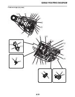
Page 76: ...CABLE ROUTING DIAGRAM 2 23 Frame and engine top view...
Page 78: ...CABLE ROUTING DIAGRAM 2 25 Frame and battery top view...
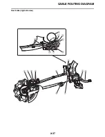
Page 80: ...CABLE ROUTING DIAGRAM 2 27 Rear brake right side view...
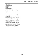
Page 82: ...CABLE ROUTING DIAGRAM 2 29 Front brake front view and right side view...
Page 84: ...CABLE ROUTING DIAGRAM 2 31 Taillight top view and right side view...
Page 86: ...CABLE ROUTING DIAGRAM 2 33...
Page 203: ...LUBRICATION SYSTEM CHART AND DIAGRAMS 5 3 1 Oil filter element 2 Oil pump...
Page 204: ...LUBRICATION SYSTEM CHART AND DIAGRAMS 5 4 1 Intake camshaft 2 Exhaust camshaft...
Page 278: ...TRANSMISSION 5 78...
Page 288: ...WATER PUMP 6 9...
Page 298: ...THROTTLE BODY 7 9...
Page 301: ......
Page 302: ...IGNITION SYSTEM 8 1 EAM20142 IGNITION SYSTEM EAM30277 CIRCUIT DIAGRAM...
Page 306: ...ELECTRIC STARTING SYSTEM 8 5 EAM20143 ELECTRIC STARTING SYSTEM EAM30279 CIRCUIT DIAGRAM...
Page 312: ...CHARGING SYSTEM 8 11 EAM20144 CHARGING SYSTEM EAM30282 CIRCUIT DIAGRAM...
Page 315: ...CHARGING SYSTEM 8 14...
Page 316: ...SIGNALING SYSTEM 8 15 EAM20154 SIGNALING SYSTEM EAM30348 CIRCUIT DIAGRAM...
Page 320: ...LIGHTING SYSTEM 8 19 EAM20153 LIGHTING SYSTEM EAM30346 CIRCUIT DIAGRAM...
Page 323: ...LIGHTING SYSTEM 8 22...
Page 324: ...COOLING SYSTEM 8 23 EAM20155 COOLING SYSTEM EAM30350 CIRCUIT DIAGRAM...
Page 327: ...COOLING SYSTEM 8 26...
Page 328: ...FUEL INJECTION SYSTEM 8 27 EAM20145 FUEL INJECTION SYSTEM EAM30284 CIRCUIT DIAGRAM...
Page 353: ...FUEL INJECTION SYSTEM 8 52...
Page 354: ...FUEL PUMP SYSTEM 8 53 EAM20146 FUEL PUMP SYSTEM EAM30287 CIRCUIT DIAGRAM...
Page 388: ...SELF DIAGNOSTIC FUNCTION AND DIAGNOSTIC CODE TABLE 9 15...
Page 398: ...CHASSIS 10 9...
Page 400: ......
Page 402: ......
Page 403: ...WR250FM 2021 WIRING DIAGRAM BAK 2819U 11_W D indd 1 2020 07 01 12 01 28...
Page 404: ...WR250FM 2021 WIRING DIAGRAM BAK 2819U 11_W D indd 2 2020 07 01 12 01 28...


