background image

– 84 –

CHAS

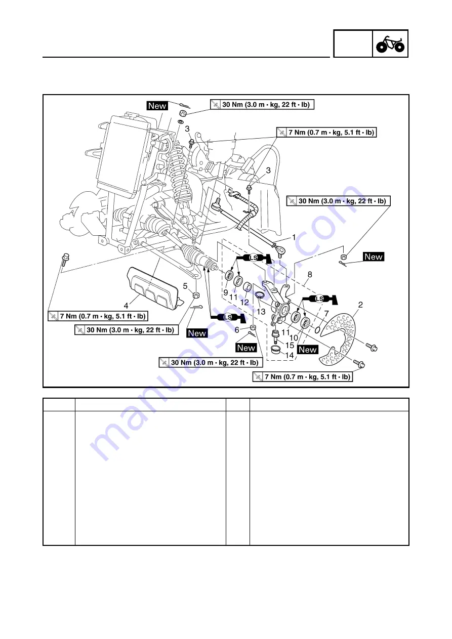
STEERING SYSTEM

Order

Job/Part

Q’ty

Remarks

8

Steering knuckle

1

Refer to “REMOVING THE STEERING 
KNUCKLE” in chapter 8.
(Manual No.: 5ND2-AE1)

9

Oil seal

1

10

Oil seal

1

11

Bearing

2

12

Spacer

1

13

Circlip

1

14

Rubber boot

1

15

Ball joint

1

For installation, reverse the removal pro-
cedure. 

Summary of Contents for WOLVERINE YFM45FXV

Page 1: ...YFM45FXV SUPPLEMENTARY SERVICE MANUAL 3C2 F8197 E0 ...

Page 2: ...t is necessary to use this Supplementary Service Manual together with the following manual YFM45FAR YFM450FAR SERVICE MANUAL 5ND2 AE1 YFM45FXV SUPPLEMENTARY SERVICE MANUAL 2005 by Yamaha Motor Co Ltd First edition July 2005 All rights reserved Any reproduction or unauthorized use without the written permission of Yamaha Motor Co Ltd is expressly prohibited ...

Page 3: ...ifications and significant changes in specifications or procedures will be forwarded to all authorized Yamaha dealers and will appear in future editions of this manual where applicable NOTE Designs and specifications are subject to change without notice IMPORTANT INFORMATION Particularly important information is distinguished in this manual by the following notations The Safety Alert Symbol means ...

Page 4: ...tify parts and clarify procedure steps there are exploded diagrams at the start of each removal and disassembly section 1 An easy to see exploded diagram 4 is provided for removal and disassembly jobs 2 Numbers 5 are given in the order of the jobs in the exploded diagram A number that is enclosed by a circle indicates a disassembly step 3 An explanation of jobs and notes is presented in an easy to...

Page 5: ...cant D Special tool E Torque F Wear limit clearance G Engine speed H Ω V A Illustrated symbols I to N in the exploded diagrams indicate the types of lubricants and lubrication points I Apply engine oil J Apply gear oil K Apply molybdenum disulfide oil L Apply wheel bearing grease M Apply lithium soap based grease N Apply molybdenum disulfide grease Illustrated symbols O to P in the exploded diagra...

Page 6: ...AND FUEL TANK 25 SEAT 25 FRONT GUARD AND FRONT FENDER 26 REAR GUARD AND REAR FENDER 27 FUEL TANK 29 FOOTREST BOARDS 31 CHASSIS 32 ADJUSTING THE REAR BRAKE 32 ADJUSTING THE SELECT LEVER CONTROL CABLE AND SHIFT ROD 34 ELECTRICAL 36 ADJUSTING THE HEADLIGHT BEAMS 36 CHANGING THE HEADLIGHT BULBS 36 ENGINE 38 ENGINE REMOVAL 38 SELECT LEVER UNIT AND COOLANT RESERVOIR 38 AIR DUCTS MUFFLER AND EXHAUST PIPE...

Page 7: ...FT 73 CHASSIS 74 FRONT AND REAR WHEELS 74 FRONT WHEELS 74 REAR WHEELS 76 INSTALLING THE REAR BRAKE DISC 78 FRONT AND REAR BRAKES 79 REAR BRAKE MASTER CYLINDER 79 STEERING SYSTEM 81 STEERING STEM 81 TIE ROD AND STEERING KNUCKLE 83 FRONT ARMS AND FRONT SHOCK ABSORBERS 85 REAR SHOCK ABSORBER AND SWINGARM 87 ELECTRICAL 89 ELECTRICAL COMPONENTS 89 CHECKING THE SWITCH 90 CHECKING THE SWITCH CONTINUITY 9...

Page 8: ...FICATION VEHICLE IDENTIFICATION NUMBER The vehicle identification number 1 is stamped into the left side of the frame MODEL LABEL The model label 1 is affixed to the frame This information will be needed to order spare parts VEHICLE IDENTIFICATION ...

Page 9: ...compression pressure at sea level 1 270 kPa 12 7 kg cm2 181 psi at 700 r min Starting system Electric starter Oil capacity Engine oil Periodic oil change 2 30 L 2 02 Imp qt 2 43 US qt With oil filter replacement 2 40 L 2 11 Imp qt 2 54 US qt Total amount 2 60 L 2 29 Imp qt 2 75 US qt Final gear case oil Periodic oil change 0 23 L 0 20 Imp qt 0 24 US qt Total amount 0 25 L 0 22 Imp qt 0 26 US qt Di...

Page 10: ...in Tread STD front 820 mm 32 28 in rear 850 mm 33 46 in Toe in 0 10 mm 0 0 39 in Tire Type Tubeless Size front AT23 8R12 rear AT23 10R12 Manufacturer front MAXXIS rear MAXXIS Type front M937 rear M938 Tire pressure cold tire Maximum load 100 kg 220 lbs Off road riding front 37 43 kPa 0 37 0 43 kgf cm2 5 3 6 1 psi rear 37 43 kPa 0 37 0 43 kgf cm2 5 3 6 1 psi Load is total weight of rider cargo and ...

Page 11: ...ot screw P S 2 1 2 turns out Float height F H 13 mm 0 51 in Fuel level F L 4 0 5 0 mm 0 16 0 20 in Above the float chamber mating surface Engine idle speed 1 450 1 550 r min Intake vacuum 32 kPa 240 mmHg 9 47 inHg Cooling system Radiator core Width 208 mm 8 19 in Height 300 mm 11 81 in Thickness 24 mm 0 94 in Radiator cap opening pressure 107 8 137 2 kPa 1 078 1 372 kg cm2 15 33 19 51 psi Radiator...

Page 12: ... mm 11 22 in Spring fitting length 231 9 mm 9 13 in Spring rate K1 16 5 N mm 1 68 kg mm 94 07 lb in Stroke K1 0 99 mm 0 3 90 in Optional spring No Rear suspension Shock absorber travel 126 mm 4 96 in Spring free length 317 mm 12 48 in Spring fitting length 283 1 mm 11 15 in Spring rate K1 31 6 N mm 3 22 kg mm 180 43 lb in Stroke K1 0 126 mm 0 4 96 in Optional spring No Front wheel Type Panel wheel...

Page 13: ... 1 Front guard and frame M8 34 3 4 24 Rear guard and frame M8 34 3 4 24 Four wheel drive switch M10 20 2 0 14 Engine side cover M6 7 0 7 5 1 Headlight and headlight bracket M6 7 0 7 5 1 Front grill and headlight bracket M6 7 0 7 5 1 Fan motor M6 8 0 8 5 8 Item Standard Limit CDI Magneto model manufacturer F4T46472 MITSUBISHI Pickup coil resistance color 459 561 Ω at 20 C 68 F White Red White Green...

Page 14: ... 7 SPEC COOLANT FLOW DIAGRAMS COOLANT FLOW DIAGRAMS 1 Radiator 2 Thermo switch 2 3 Fan motor È To coolant reservoir ...

Page 15: ... 8 SPEC COOLANT FLOW DIAGRAMS 1 Radiator 2 Thermostat ...

Page 16: ...witch 6 Rear brake switch lead 7 Starter cable 8 Rear brake cable 9 Front brake hose 0 Front brake light switch lead A Main switch lead B Coolant reservoir hose C Coolant reservoir breather hose D Differential gear case breather hose E Sub wire harness 1 F Fan motor breather hose G Fan motor lead C D B E G Í 1 2 3 A A D F 0 E 2 É Ê4 5 6 7 8 0 9 È 8 7 6 4 A B C 9 3 Ì Ë ...

Page 17: ...he handlebar with a plastic band Ë Pass the rear brake cable through the cable guide making sure that it is routed on the right side of the steering stem Ì Fasten the on command four wheel drive switch lead front brake light switch lead handlebar switch lead and rear brake switch lead with a plastic band Í Fasten the sub wire harness 1 coolant reservoir breather hose coolant reservoir hose differe...

Page 18: ... 11 SPEC CABLE ROUTING 1 Auxiliary DC jack optional 2 Headlight lead 3 Headlight coupler A A A A 1 2 2 3 ...

Page 19: ...e breather hose A Thermo switch 2 È Insert the fuel tank breather hose into the hole of the handlebar cover É Fasten the starter cable with a plastic band Ê Fasten the radiator outlet hose with a plastic band Ë Fasten the coolant reservoir breather hose cool ant reservoir hose and radiator outlet hose with the plastic bands Ì Fasten the sub wire harness 1 with the plastic bands Ï Ï 1 2 3 4 9 0 A C...

Page 20: ... breather hose with a plastic band Î Fasten the sub wire harness 1 differential gear case breather hose coolant reservoir hose and coolant reservoir breather hose with a plastic band Ï 7 17 mm 0 28 0 67 in Ï Ï 1 2 3 4 9 0 A C B C A Ì Ë Ì Ë Ê B B C C A 8 7 7 7 6 5 8 8 9 È É Í Î C C B ...

Page 21: ...il brake light lead 8 Air filter case check hose 9 Water pump breather hose 0 Speed sensor lead A A C magneto lead B Radiator outlet hose C Starter cable D Float chamber air vent hose E Neutral switch lead F Park switch G Reverse switch lead H Rectifier regulator D D F C E A B C B E F A D D Í Î Ï È É Ê Ê Ë Ì Ð E F G H 8 8 8 9 9 0 0 A A B C D 1 1 2 2 3 3 3 4 4 5 5 6 7 ...

Page 22: ...c bands Ë Fasten the tail brake light lead with a plastic band Ì Fasten the wire harness negative battery lead sub wire harness 2 A C magneto lead speed sensor lead and final drive gear case breather hose with a plastic band Í 10 30 Î 45 55 Ï Fasten the water pump breather hose with a plastic holder Ð Fasten the wire harness with the plastic holder D D F C E A B C B E F A D D Í Î Ï È É Ê Ê Ë Ì Ð E...

Page 23: ...r control cable 0 Rear brake hose A Ignition coil B Sub wire harness 3 È Fasten the select lever control cable with the plastic holder É Fasten the select lever control cable and rear brake light switch lead with the plastic bands Ê Fasten the rear brake hose with the plastic holder Ë Fasten the rear brake hose with the plastic bands A A B B C D C D A A B B Ë Ë É È É Ê 8 9 0 0 0 A B 1 2 3 4 5 6 7 ...

Page 24: ...adlight leads 0 Front brake light switch coupler A On command four wheel drive switch coupler B Sub wire harness 3 coupler C Main switch coupler D Handlebar switch couplers E Rear brake switch coupler F Coolant reservoir breather hose G Differential gear case breather hose H Fan motor breather hose I Sub wire harness 3 lead J Meter assembly leads B B A A B B B B 7 1 2 3 4 5 5 6 8 E 9 9 0 F G H I J...

Page 25: ...r air vent hose with the plastic holders Ê Route the headlight lead under the couplers Ë Pass the hoses through the holes in the air duct bracket The end of each hose should extend approximately 25 mm 0 98 in past the bracket B B A A B B B B 7 1 2 3 4 5 5 6 8 E 9 9 0 F G H I J A B C D È È È É È Ê Ë ...

Page 26: ...il brake light lead 4 Headlight relay 5 CDI unit 6 Fuse box 7 Starter relay 8 Starter motor lead 9 Negative battery lead È Fasten the positive battery lead with the plastic holders É Route the starter relay lead under the fuse box A A A A É È 8 9 1 2 3 3 4 5 6 7 ...

Page 27: ...reather hose 2 Rear brake hose 3 Air filter case check hose È Fasten the final drive gear case breather hose with the plastic holder É Fasten the rear brake hose with the plastic hold ers Ê Pass the rear brake hose through the hose guides È É 1 2 3 Ê ...

Page 28: ...mi or hours maintenance intervals However keep in mind that if the ATV isn t used for a long period of time the month maintenance intervals should be followed Items marked with an asterisk should be performed by a Yamaha dealer as they require special tools data and technical skills ITEM ROUTINE Whichever comes first INITIAL EVERY month 1 3 6 6 12 km mi 320 200 1 300 800 2 500 1 600 2 500 1 600 5 ...

Page 29: ... or dusty areas Engine oil Replace Warm engine before draining Engine oil filter car tridge Replace Engine oil strainer Clean Final gear oil Check oil level oil leakage Replace every 12 months Differential gear oil Front brake Check operation fluid leakage See NOTE page 22 Correct if necessary Rear brake Check operation fluid leakage See NOTE page 22 Correct if necessary Select lever safety system...

Page 30: ... necessary Check fluid level and ATV for fluid leakage and correct if necessary Replace brake pads Whenever worn to the limit 6 Rear brake Check operation and correct if necessary Check brake lever free play and adjust if necessary Check fluid level and ATV for fluid leakage and correct if necessary Replace brake pads Whenever worn to the limit 7 Brake hoses Check for cracks or other damage and re...

Page 31: ...for oil leakage and correct if necessary 25 Engine oil filter cartridge Replace 26 Engine oil strainer Clean 27 Differential gear oil Change Check ATV for oil leakage and correct if necessary 28 Final gear oil Change Check ATV for oil leakage and correct if necessary 29 Cooling system Check coolant level and ATV for coolant leakage and correct if necessary Replace coolant Every 2 years 30 Moving p...

Page 32: ... m kg 5 1 ft Ib Order Job Part Q ty Remarks Removing the seat Remove the parts in the order below 1 Seat 1 NOTE Pull rearward on the seat lock lever located on the left rear of the frame and then pull up on the rear of the seat 2 Engine side panel 1 3 Engine side cover 1 For installation reverse the removal pro cedure ...

Page 33: ...er Job Part Q ty Remarks Removing the front guard and front fender Remove the parts in the order below Seat Refer to SEAT 1 Front panel 1 2 Engine skid plate 1 3 Front guard 1 4 Headlight coupler 2 Disconnect 5 Headlight 2 6 Front grill 1 7 Main switch coupler 1 Disconnect 8 Handlebar cover 1 9 Fuel tank cover 1 10 Meter assembly coupler 2 Disconnect 11 Front fender 1 For installation reverse the ...

Page 34: ...r fender Remove the parts in the order below Seat Refer to SEAT Fuel tank cover Refer to FRONT GUARD AND FRONT FENDER 1 Rear guard 1 2 Battery holding bracket 1 3 Battery lead 2 Disconnect CAUTION First disconnect the negative lead then disconnect the positive lead 4 Battery 5 Starter motor lead 1 Disconnect 6 Tail brake light coupler 1 Disconnect 7 CDI unit 1 ...

Page 35: ... 28 CHK ADJ SEAT FENDERS AND FUEL TANK 2 5 4 3 8 7 9 6 6 1 T R 34 Nm 3 4 m kg 24 ft Ib 6 Order Job Part Q ty Remarks 8 Wire harness 1 9 Rear fender 1 For installation reverse the removal pro cedure ...

Page 36: ... the parts in the order below Seat Refer to SEAT Front fender Refer to FRONT GUARD AND FRONT FENDER 1 Fuel hose 1 NOTE Before disconnecting the fuel hose turn the fuel cock to OFF 2 Fuel cock lever 1 3 Fuel tank 1 NOTE When installing the fuel tank pass the fuel tank breather hose through the hole of the handlebar cover 4 Air duct assembly 1 upper 1 5 Float chamber air vent hose 1 ...

Page 37: ... SEAT FENDERS AND FUEL TANK 7 3 4 2 6 6 5 6 1 T R 10 Nm 1 0 m kg 7 2 ft Ib T R 10 Nm 1 0 m kg 7 2 ft Ib Order Job Part Q ty Remarks 6 Plastic band 4 7 Rubber cover 1 For installation reverse the removal pro cedure ...

Page 38: ...OOTREST BOARDS Order Job Part Q ty Remarks Removing the footrest boards Remove the parts in the order below 1 Left footrest board 1 2 Right footrest board 1 3 Footrest board bracket 4 For installation reverse the removal pro cedure ...

Page 39: ...t of specification Adjust Rear brake lever free play 0 5 2 0 mm 0 02 0 08 in 2 Check brake pedal height a Out of specification Adjust 1 Brake pedal 2 Footrest board bracket Brake pedal height 67 77 mm 2 64 3 03 in 3 Adjust rear brake lever free play brake pedal height a Loosen the locknut handlebar 1 and fully screw in the brake lever cable adjuster han dlebar 2 b Remove the rear brake master cyli...

Page 40: ...Hold the adjusting nut 7 and tighten the locknut 6 i Turn the brake lever cable adjuster handle bar 2 until the rear brake lever free play c is within the specified limits j Tighten the locknut handlebar 1 k Adjust the select lever control cable Refer to ADJUSTING THE SELECT LEVER CONTROL CABLE AND SHIFT ROD l Install the rear brake master cylinder cover WARNING After this adjustment is performed ...

Page 41: ... master cylinder cover 1 b Make sure the select lever is in NEUTRAL c Adjust the control cable so there is zero free play in the cable When the adjustment is correct slack in the return spring 2 will be taken up NOTE In some cases it will be necessary to further adjust the cable with the locknuts 3 arrange ment that holds the cable to its mount d When the brake begins to work a 20 30 mm 0 8 1 2 in...

Page 42: ...ation of the select lever is incor rect adjust the select lever control cable 4 with the adjuster 5 Select lever shift rod a Make sure the select lever is in NEUTRAL b Loosen both locknuts 1 c Adjust the shift rod length for smooth and correct shifting d Tighten the locknuts 1 to specification T R Locknut 15 Nm 1 5 m kg 11 ft lb ...

Page 43: ...n direction a or b Direction a Headlight beam is raised Direction b Headlight beam is lowered CHANGING THE HEADLIGHT BULBS 1 Remove cover 1 2 Remove bulb holder 1 bulb NOTE To remove the bulb holder push it inward and turn it counterclockwise WARNING Keep flammable products and your hands away from the bulb while it is on since it will be hot Do not touch the bulb until it cools down ...

Page 44: ...UTION Avoid touching the glass part of the bulb Keep it free from oil otherwise the trans parency of the glass life of the bulb and luminous flux will be adversely affected If oil gets on the bulb thoroughly clean it with a cloth moistened with alcohol or lac quer thinner 4 Install bulb holder cover New ...

Page 45: ...er below Engine oil Drain Refer to CHANGING THE ENGINE OIL in chapter 3 Manual No 5ND2 AE1 Front fender rear fender fuel tank rub ber cover Refer to SEAT FENDERS AND FUEL TANK Footrest boards Refer to FOOTREST BOARDS Coolant Drain Refer to CHANGING THE COOLANT in chapter 3 Manual No 5ND2 AE1 Carburetor assembly Refer to CARBURETOR in chapter 6 Manual No 5ND2 AE1 ENGINE REMOVAL ...

Page 46: ... Order Job Part Q ty Remarks 1 Shift arm 1 2 Select lever shift rod 1 3 Select lever unit 1 4 Coolant reservoir breather hose 1 5 Coolant reservoir hose 1 6 Coolant reservoir 1 For installation reverse the removal pro cedure ...

Page 47: ...e the parts in the order below 1 Air duct assembly 1 upper 1 2 Air duct assembly 1 lower 1 3 Muffler 1 4 Exhaust pipe stay 1 5 Exhaust pipe gasket 1 1 6 Air duct assembly 2 1 7 Final drive gear case breather hose 1 8 Cylinder head breather hose 1 9 Air filter case 1 10 Engine bracket upper 1 For installation reverse the removal pro cedure ...

Page 48: ...R PUMP in chapter 5 Manual No 5ND2 AE1 1 Cylinder head breather hose 1 2 Spark plug lead 1 3 Thermo switch 1 lead 1 4 Starter motor lead 1 5 A C magneto lead coupler 2 6 Speed sensor lead coupler 1 7 Reverse switch lead 1 Green White 8 Neutral switch lead 1 Sky blue 9 Park switch lead 1 Blue Red 10 Engine ground lead 1 For installation reverse the removal pro cedure ...

Page 49: ...ighten exhaust pipe nut 4 muffler bolt front side 5 muffler bolt rear side 6 exhaust pipe stay bolt drive belt cover side 7 exhaust pipe stay bolt exhaust pipe side 8 muffler and exhaust pipe bolt 9 T R 20 Nm 2 0 m kg 14 ft lb T R 25 Nm 2 5 m kg 18 ft lb T R 25 Nm 2 5 m kg 18 ft lb T R 10 Nm 1 0 m kg 7 2 ft lb T R 14 Nm 1 4 m kg 10 ft lb T R 15 Nm 1 5 m kg 11 ft lb ...

Page 50: ... case Refer to SEAT FENDERS AND FUEL TANK Air duct assembly 1 upper and lower exhaust pipe muffler Refer to ENGINE REMOVAL Carburetor assembly Refer to CARBURETOR in chapter 6 Manual No 5ND2 AE1 Timing plug Refer to ADJUSTING THE VALVE CLEARANCE in chapter 3 Manual No 5ND2 AE1 Thermostat Refer to THERMOSTAT in chapter 5 Manual No 5ND2 AE1 1 Spark plug lead 1 2 Spark plug 1 ...

Page 51: ...er O ring 2 2 6 Thermo switch 1 lead 1 Disconnect 7 Timing chain tensioner cap bolt 1 Refer to REMOVING THE CYLINDER HEAD and INSTALLING THE CYLIN DER HEAD 8 Timing chain tensioner gasket 1 1 9 Camshaft sprocket 1 10 Cylinder head 1 11 Cylinder head gasket 1 12 Dowel pin 2 13 O ring 1 For installation reverse the removal pro cedure ...

Page 52: ...er T D C on the compression stroke there should be clearance between the valve stem tips and their respective rocker arm adjusting screws If there is no clearance rotate the crankshaft counterclockwise one turn 2 Loosen camshaft sprocket bolt 1 NOTE When loosening the bolt use a wrench 2 to hold the collar 3 Loosen timing chain tensioner cap bolt 4 Remove timing chain tensioner camshaft sprocket N...

Page 53: ...otate the camshaft to align the camshaft pin 1 with the cylinder head match mark 2 b Turn the crankshaft counterclockwise with a wrench c Align the T mark 3 on the rotor with the stationary pointer 4 on the A C magneto cover When the T mark is aligned with the stationary pointer the piston is at the Top Dead Center T D C CAUTION Do not turn the crankshaft during the cam shaft sprocket installation...

Page 54: ...er head match mark 2 i If the marks are aligned tighten the cam shaft sprocket bolt If the marks are not aligned change the meshing position of the camshaft sprocket and timing chain 3 Install timing chain tensioner a Remove the tensioner cap bolt 1 washer 2 and spring 3 b Release the timing chain tensioner one way cam 4 and push the tensioner rod 5 all the way in c Install the tensioner 6 with a ...

Page 55: ...CYLINDER HEAD 4 Tighten camshaft sprocket bolt 1 NOTE When tightening the bolt use a wrench 2 to hold the collar 5 Check camshaft sprocket I mark rotor T mark Out of alignment Adjust T R 60 Nm 6 0 m kg 43 ft lb ...

Page 56: ...Refer to CHANGING THE ENGINE OIL in chapter 3 Manual No 5ND2 AE1 Seat Refer to SEAT FENDERS AND FUEL TANK Left footrest board Refer to FOOTREST BOARDS 1 Access cover 1 2 A C magneto coupler 2 Disconnect 3 Collar 1 Refer to REMOVING THE A C MAG NETO and INSTALLING THE A C MAGNETO 4 A C magneto cover gasket 1 1 5 Dowel pin 2 6 Lead holder 1 ...

Page 57: ...tator assembly 1 9 Rotor 1 Refer to REMOVING THE A C MAG NETO and INSTALLING THE A C MAGNETO 10 Starter wheel gear 1 11 Woodruff key 1 12 Washer 1 13 Starter idle gear shaft 1 14 Washer bearing 1 1 15 Starter idle gear 1 For installation reverse the removal pro cedure ...

Page 58: ... all of them are loosened 3 Remove rotor 1 NOTE Use the flywheel puller 2 Flywheel puller P N YM 01404 90890 01404 INSTALLING THE A C MAGNETO 1 Apply sealant Quick Gasket 1 into the slit 2 Install woodruff key rotor NOTE Before installing the rotor clean the outside of the crankshaft and the inside of the rotor After installing the rotor check that the rotor rotates smoothly If not reinstall the k...

Page 59: ...from the outside This will make assembly easier Be careful not to damage the oil seal Tighten the bolts in stages using a criss cross pattern New T R 10 Nm 1 0 m kg 7 2 ft lb 4 Install collar 1 NOTE When tightening the rotor bolt use a wrench 2 to hold the collar Before installing the collar do not forget to install the O ring T R 50 Nm 5 0 m kg 36 ft lb ...

Page 60: ...Engine assembly Refer to ENGINE REMOVAL in chapter 4 Manual No 5ND2 AE1 Cylinder head Refer to CYLINDER HEAD Cylinder and piston Refer to CYLINDER AND PISTON in chapter 4 Manual No 5ND2 AE1 Rotor Refer to A C MAGNETO Primary sheave secondary sheave Refer to PRIMARY AND SECONDARY SHEAVES in chapter 4 Manual No 5ND2 AE1 Clutch carrier assembly Refer to CLUTCH in chapter 4 Manual No 5ND2 AE1 ...

Page 61: ...P DRIVE GEAR and INSTALLING THE OIL PUMP DRIVE GEAR in chapter 4 Manual No 5ND2 AE1 2 Oil pump driven gear 1 3 Timing chain guide 1 4 Timing chain 1 5 Starter motor O ring 1 1 6 Oil filter cartridge 1 7 Speed sensor 1 8 Shift cam stopper 1 9 Neutral switch 1 10 Park switch 1 11 Reverse switch 1 12 Oil filler cap 1 ...

Page 62: ...RANKCASE Order Job Part Q ty Remarks 13 Bearing cover gasket 1 1 14 Oil delivery pipe 1 15 Oil strainer cover O ring 1 1 16 Compression spring 1 17 Oil strainer 1 For installation reverse the removal pro cedure ...

Page 63: ...nsmission Remove the parts in the order below Crankcase separation Refer to CRANKCASE in chapter 4 Manual No 5ND2 AE1 1 Driven sprocket 1 2 Chain 1 3 Guide bar 1 4 Shift fork 1 5 Spring 1 6 Clutch dog 1 7 Low wheel gear 1 8 Secondary shaft 1 9 Middle driven gear 1 10 Drive axle 1 ...

Page 64: ...ENG TRANSMISSION Order Job Part Q ty Remarks 11 Shift cam 1 12 Middle drive gear 1 13 Stopper wheel 1 14 Stopper lever 1 15 Stopper lever shaft 1 16 Spacer 1 For installation reverse the removal pro cedure ...

Page 65: ... REMOVING THE MIDDLE DRIVEN SHAFT and INSTALLING THE MIDDLE DRIVEN SHAFT in chap ter 4 Manual No 5ND2 AE1 2 Bearing 2 3 Universal joint 1 4 Universal joint yoke 1 5 Bearing housing 1 6 Shim Refer to SELECTING THE MIDDLE DRIVE AND DRIVEN GEAR SHIMS in chapter 4 Manual No 5ND2 AE1 7 Middle drive pinion gear 1 Refer to REMOVING THE MIDDLE DRIVEN SHAFT and INSTALLING THE MIDDLE DRIVEN SHAFT in chap te...

Page 66: ...IDDLE GEAR Order Job Part Q ty Remarks 9 Damper cam 1 10 Spring 1 11 Gear coupling 1 12 Front drive shaft coupling 1 13 Bearing retainer 1 14 Middle driven shaft 1 For installation reverse the removal pro cedure ...

Page 67: ...headlights front grill Refer to SEAT FENDERS AND FUEL TANK Left footrest board Refer to FOOTREST BOARDS Coolant Drain Refer to CHANGING THE COOLANT in chapter 3 Manual No 5ND2 AE1 1 Fan motor coupler 1 Disconnect 2 Thermo switch 2 coupler 1 Disconnect 3 Coolant reservoir hose 1 Disconnect 4 Fan motor breather hose 1 Disconnect 5 Radiator inlet hose 1 Disconnect 6 Radiator outlet hose 1 Disconnect ...

Page 68: ...61 COOL RADIATOR 8 4 5 6 7 1 4 2 9 3 T R 7 Nm 0 7 m kg 5 1 ft Ib T R 8 Nm 0 8 m kg 5 8 ft Ib Order Job Part Q ty Remarks 8 Fan motor 1 9 Thermo switch 2 1 For installation reverse the removal pro cedure ...

Page 69: ...AT FENDERS AND FUEL TANK Differential gear oil Drain Refer to CHANGING THE DIFFEREN TIAL GEAR OIL in chapter 3 Manual No 5ND2 AE1 Steering knuckle Refer to STEERING SYSTEM Front arms lower Refer to FRONT ARMS AND FRONT SHOCK ABSORBERS Rear brake master cylinder cover Refer to FRONT AND REAR BRAKES 1 Constant velocity joint 2 2 Gear motor coupler four wheel drive switch connector 1 1 Disconnect FRO...

Page 70: ...FERENTIAL GEAR Order Job Part Q ty Remarks 3 Differential gear case breather hose 1 Disconnect 4 Differential gear assembly 1 5 Front drive shaft 1 6 Compression spring 1 7 Front drive shaft coupling 1 For installation reverse the removal pro cedure ...

Page 71: ... constant velocity joints Remove the parts in the order below 1 Circlip 1 2 Boot band 2 Refer to ASSEMBLING THE FRONT CONSTANT VELOCITY JOINTS 3 Boot band 2 4 Dust boot 2 5 Circlip 1 6 Double off set joint 1 7 Circlip 1 8 Ball bearing 1 9 Joint shaft assembly 1 For assembly reverse the disassembly procedure ...

Page 72: ... Remove the parts in the order below 1 Gear motor O ring 1 1 2 Four wheel drive switch 1 3 Dust seal 1 4 Circlip 1 5 Coupling gear bearing circlip 1 1 1 6 Stopper bolt shaft 1 1 7 Shift fork sliding gear 1 8 Shift fork 1 9 2WD 4WD shift sleeve 1 0 Differential gear case cover O ring 1 1 A Shim left B Differential gear unit 1 ...

Page 73: ...FRONT CONSTANT VELOCITY JOINTS AND DIFFERENTIAL GEAR Order Job Part Q ty Remarks C Shim right D Circlip bearing 1 1 E Drive pinion gear 1 F Differential gear case 1 For assembly reverse the disassembly procedure ...

Page 74: ...eans of specialized equipment Do not attempt to disassemble this unit Disassembly will result in the malfunction of the unit CHECKING THE CONSTANT VELOCITY JOINTS 1 Check double off set joint spline ball joint spline shaft spline Wear damage Replace 2 Check dust boots Cracks damage Replace CAUTION Always use new boot bands 3 Check balls and ball races inner surface of double off set joint Pitting ...

Page 75: ...eplace Move the spring up and down 3 Check front drive shaft Bends Replace WARNING Do not attempt to straighten a bent shaft this may dangerously weaken the shaft ASSEMBLING THE FRONT CONSTANT VELOCITY JOINTS 1 Apply molybdenum disulfide grease into the ball joint assembly NOTE Molybdenum disulfide grease is included in the repair kit 2 Install dust boots 1 dust boot bands 2 3 a Apply molybdenum d...

Page 76: ... THE DIFFERENTIAL GEAR LASH 2 Install gear motor a Make sure that the gear motor and shift fork sliding gear are in the 2WD position b While aligning the gear motor stopper a with the differential gear case boss b mesh the pinion gear gear motor and shift fork sliding gear together c Push the gear motor into the differential gear case d Rotate the gear motor counterclockwise until it lines up with...

Page 77: ...ND ADJUSTING THE DIFFERENTIAL GEAR LASH Measuring the differential gear lash 1 Secure the gear case in a vise or another supporting device 2 Remove drain plug gasket 3 Install a bolt of the specified size 1 into the drain plug hole CAUTION Finger tighten the bolt until it holds the ring gear Otherwise the ring gear will be dam aged 4 Attach gear lash measurement tool 1 dial gauge 2 a Measuring poi...

Page 78: ... 0 10 0 50 mm 0 004 0 020 in Adjusting differential gear lash 1 Remove shim s left 1 differential gear unit 2 shim s right 3 2 Adjust gear lash a Select the suitable shims using the following chart b If it is necessary to increase by more than 0 05 mm 0 002 in Reduce right shim thickness by 0 1 mm 0 004 in for every 0 1 mm 0 004 in of left shim increase Too little gear lash Reduce shim thickness T...

Page 79: ...and under the frame 2 Remove the wheel cap and cotter pin from the axle nut right or left 3 Measure the starting torque of the front wheel i e differential gear preload with the torque wrench NOTE Repeat this step several times to obtain an average figure During this test the other front wheel will turn in the opposite direction 4 Out of specification Replace the differen tial gear assembly 5 With...

Page 80: ... gear oil Drain Refer to CHANGING THE FINAL GEAR OIL in chapter 3 Manual No 5ND2 AE1 Rear wheel hubs brake disc Refer to FRONT AND REAR WHEELS 1 O ring 1 2 Rear axle dust cover 1 1 Refer to REMOVING THE REAR AXLE and INSTALLING THE FINAL DRIVE GEAR in chapter 7 Manual No 5ND2 AE1 3 Final drive gear case breather hose 1 Disconnect 4 Final drive gear assembly 1 5 Rear drive shaft 1 For installation ...

Page 81: ...e vehicle so there is no danger of it falling over 1 Front wheel 1 Refer to INSTALLING THE WHEEL in chapter 8 Manual No 5ND2 AE1 2 Wheel cap 1 Refer to INSTALLING THE WHEEL HUB in chapter 8 Manual No 5ND2 AE1 3 Cotter pin 1 4 Axle nut 1 5 Brake caliper assembly 1 NOTE Do not squeeze the brake lever when the brake caliper is off of the brake disc as the brake pads will be forced shut FRONT AND REAR...

Page 82: ... 75 CHAS FRONT AND REAR WHEELS Order Job Part Q ty Remarks 6 Wheel hub 1 7 Brake disc 1 For installation reverse the removal pro cedure ...

Page 83: ...vehicle on a level surface WARNING Securely support the vehicle so there is no danger of it falling over 1 Rear wheel 2 Refer to INSTALLING THE WHEEL in chapter 8 Manual No 5ND2 AE1 2 Wheel cap 2 Refer to INSTALLING THE WHEEL HUB in chapter 8 Manual No 5ND2 AE1 3 Cotter pin 2 4 Axle nut 2 5 Wheel hub 2 6 Brake caliper 1 7 Brake disc bracket 1 ...

Page 84: ... 77 CHAS FRONT AND REAR WHEELS Order Job Part Q ty Remarks 8 Brake disc 1 Refer to INSTALLING THE REAR BRAKE DISC 9 Brake disc guard 1 For installation reverse the removal pro cedure ...

Page 85: ...LS INSTALLING THE REAR BRAKE DISC 1 Install brake disc 1 NOTE Make sure that the OUT mark on the brake disc faces the brake disc bracket 2 Apply locking agent LOCTITE to the threads of brake disc bolts T R 28 Nm 2 8 m kg 20 ft lb ...

Page 86: ... fender Refer to SEAT FENDERS AND FUEL TANK Brake fluid Drain 1 Brake fluid reservoir cap 1 2 Brake fluid reservoir diaphragm holder 1 3 Brake fluid reservoir diaphragm 1 4 Brake fluid reservoir 1 5 Brake master cylinder cover 1 6 Brake fluid reservoir hose 1 7 Union bolt 1 Refer to INSTALLING THE REAR BRAKE MASTER CYLINDER in chap ter 8 Manual No 5ND2 AE1 8 Copper washer 2 9 Brake hose 1 ...

Page 87: ...rake cable 1 Disconnect 11 Bracket 1 12 Brake master cylinder 1 13 Hose joint 1 14 Brake pedal 1 15 Select lever control cable 1 Disconnect 16 Rear brake light switch 1 17 Bracket 1 18 Brake master cylinder bracket 1 For installation reverse the removal pro cedure ...

Page 88: ... below Handlebar Refer to HANDLEBAR in chapter 8 Manual No 5ND2 AE1 Seat front fender Refer to SEAT FENDERS AND FUEL TANK Radiator Refer to RADIATOR 1 Lock washer 1 Refer to INSTALLING THE CABLE GUIDE in chapter 8 Manual No 5ND2 AE1 2 Cable guide 1 3 Steering stem bushing 2 4 Spacer 2 5 Oil seal 2 6 Tie rod end nut 2 7 Tie rod 2 Disconnect ...

Page 89: ...g stem nut 1 9 Pitman arm 1 10 Steering stem 1 11 Oil seal 1 12 Bearing retainer 1 Refer to REMOVING THE BEARING RETAINER and INSTALLING THE BEARING RETAINER in chapter 8 Manual No 5ND2 AE1 13 Bearing 1 14 Oil seal 1 For installation reverse the removal pro cedure ...

Page 90: ...ng knuckle Remove the parts in the order below Front fender Refer to SEAT FENDERS AND FUEL TANK Front wheel brake disc Refer to FRONT AND REAR WHEELS 1 Tie rod 1 Refer to INSTALLING THE TIE ROD in chapter 8 Manual No 5ND2 AE1 2 Brake disc guard 1 3 Brake hose holder bolt 2 4 Protector 1 5 Nut 1 6 Nut 1 7 O ring 1 ...

Page 91: ... Remarks 8 Steering knuckle 1 Refer to REMOVING THE STEERING KNUCKLE in chapter 8 Manual No 5ND2 AE1 9 Oil seal 1 10 Oil seal 1 11 Bearing 2 12 Spacer 1 13 Circlip 1 14 Rubber boot 1 15 Ball joint 1 For installation reverse the removal pro cedure ...

Page 92: ...marks Removing the front arms and front shock absorbers Remove the parts in the order below Engine skid plate front fender Refer to SEAT FENDERS AND FUEL TANK Front wheel brake disc Refer to FRONT AND REAR WHEELS 1 Air duct assembly 1 upper 1 2 Air duct assembly 1 lower 1 3 Brake disc guard 1 4 Protector 1 ...

Page 93: ... ARMS and INSTALLING THE FRONT ARMS AND FRONT SHOCK ABSORBER in chapter 8 Manual No 5ND2 AE1 6 Nut 1 7 Bolt nut 2 2 8 Front lower arm bushing 1 2 9 Nut bolt 2 2 10 Front shock absorber 1 11 Bolt nut 2 2 12 Front upper arm bushing 1 2 13 Circlip 1 14 Ball joint 1 For installation reverse the removal pro cedure ...

Page 94: ...e order below Rear wheel hubs brake disc Refer to FRONT AND REAR WHEELS Rear brake caliper brake hose Refer to FRONT AND REAR BRAKES in chapter 8 Manual No 5ND2 AE1 Final drive gear assembly Refer to REAR AXLE FINAL DRIVE GEAR AND DRIVE SHAFT 1 Clip washer pin 1 1 1 2 Nut bolt 1 1 3 Rear shock absorber 1 4 Spacer 2 5 Final drive gear case breather hose 1 6 Metal clamp 1 ...

Page 95: ...7 Rear axle housing 1 Refer to INSTALLING THE REAR AXLE HOUSING in chapter 8 Manual No 5ND2 AE1 8 Nut bolt 2 2 Refer to REMOVING THE SWING ARM in chapter 8 Manual No 5ND2 AE1 9 Swingarm bushing 1 2 10 Spring rubber boot 1 1 For installation reverse the removal pro cedure ...

Page 96: ...ke light 7 Headlight relay 8 Fuse box 9 Main fuse 0 Starter relay A CDI unit B Rectifier regulator C Reverse switch D Park switch E Neutral switch F Speed sensor G Diode H Rear brake light switch I Gear motor J Thermo switch 2 K Fan L Headlight M Circuit breaker fan N Ignition coil 1 2 3 4 5 6 7 9 0 A B E D C F J K M N I H L G 8 ELECTRICAL COMPONENTS ...

Page 97: ...ty between lead terminals Poor connection no continuity Correct or replace The coupler locations are circled L B Y G Br L B BLACK 1 4 5 C 6 2 3 R B R W PUSH Br L Y G B R W Br L Br R R B L B Br R L R L B L G B GRAY ON OFF R Br Br L Br Y BLACK 7 B B BLACK 8 9 B B Br R L R L G B L B 2WD 4WD B A 0 Br L Br R W R ON OFF R W R Br Br L OFF ...

Page 98: ...ch 2 Engine stop switch 3 Start switch 4 On command four wheel drive switch 5 Main switch 6 Rear brake light switch 7 Front brake light switch 8 Rear brake switch 9 Four wheel drive switch 0 Reverse switch A Park switch B Neutral switch C Fuse ...

Page 99: ... R R R R B W W W R B R R B B B B B B R R R G W Sb L R G W Sb B Sb B G W B A L R L R O R P B W L W B L R W R G B R W R G B Y G B Y G B Y G B L Y Y B G BLACK Sb Br W B R B R B R A L B B Sb Br W L B Sb Br W L B Sb Br L Br R Br R Br L L B R B Br L R W R W Br L R Y Br L Br R B R B R B R Y P P B B B Y G Y B L L L BLACK BLACK R B R W R B R W B G Y B L Y Y G B DARK GRAY BLACK BLACK L R B Br Y Y Br Br Y BL...

Page 100: ... R R B W W W R B R R B B B B B B R R R G W Sb L R G W Sb B Sb B G W B A L R L R O R P B W L W B L R W R G B R W R G B Y G B Y G B Y G B L Y Y B G BLACK Sb Br W B R B R B R A L B B Sb Br W L B Sb Br W L B Sb Br L Br R Br R Br L L B R B Br L R W Br L Br R B R B R B P P B B B L L BLACK BLACK R B R W R B R W B Y Y G B DARK GRAY BLACK BLACK L R B Br Y Y Br Br Y BLACK BLACK Br Y G L A B B W L Br R Sb L ...

Page 101: ...er Use the following special tool s for trouble shooting Pocket tester P N YU 03112 C 90890 03112 EB802011 CONTINUITY 1 Fuses main headlight Refer to CHECKING THE SWITCH NO CONTINUITY Replace the fuse EB802012 CORRECT 2 Battery Check the battery condition Refer to CHECKING THE BATTERY in chapter 3 Manual No 5ND2 AE1 Open circuit voltage 12 8 V or more at 20 C 68 F INCORRECT Clean the battery termi...

Page 102: ...reen terminal 2 Battery terminal Yellow terminal 3 Battery terminal Black terminal 4 Tester lead Blue terminal 1 Tester lead Yellow terminal 5 Check the headlight relay for continuity NO CONTINUITY Replace the headlight relay EB805013 CORRECT 6 Wiring connections Check the connections of the entire light ing system Refer to CIRCUIT DIAGRAM Check the condition of each of the lighting system s circu...

Page 103: ...L G W R O O C B O O W L W Sb L B B W B L B W B W W W W W W W R R R R B W W W R B R R B B B B B B R R R G W Sb L R G W Sb B Sb B G W B A L R L R O R P B W L W B L R W R G B R W R G B Y G B Y G B Y G B L Y Y B G BLACK Sb Br W B R B R B R A L B B Sb Br W L B Sb Br W L B Sb Br L Br R Br R Br L L B R B Br L R W R W Br L R Y Br L Br R B R B R B R Y P P B B B Y G Y B L L L BLACK BLACK R B R W R B R W B G...

Page 104: ...tral indicator light G Reverse indicator light H Park indicator light I Four wheel drive indicator light J Coolant temperature warning light K Reverse switch L Neutral switch M Park switch N Thermo switch 1 T Gear motor W Ignition fuse a Signaling system fuse b Front brake light switch c Rear brake light switch d Tail brake light ...

Page 105: ...ONTINUITY Replace the neutral switch CONTINUITY 2 Park switch Refer to CHECKING THE SWITCH NO CONTINUITY Replace the park switch CONTINUITY 3 Reverse switch Refer to CHECKING THE SWITCH NO CONTINUITY Replace the reverse switch CONTINUITY 4 Four wheel drive switch Refer to CHECKING THE SWITCH Replace the meter assembly NO CONTINUITY Replace the four wheel drive switch ...

Page 106: ... W W W W R R R R B W W W R B R R B B B B B B R R R G W Sb L R G W Sb B Sb B G W B A L R L R O R P B W L W B L R W R G B R W R G B Y G B Y G B Y G B L Y Y B G BLACK Br W B R B R B R A L B B Br W L B Sb Br W L B Sb Br L Br R Br R Br L L B R B Br L R W R W Br L R Y Br L Br R B R B R B R Y P P B B B Y G Y B L L L BLACK BLACK R B R W R B R W B G Y B L Y Y G B DARK GRAY BLACK BLACK L R B Br Y Y Br Br Y ...

Page 107: ... Front fender Use the following special tool s for trouble shooting Pocket tester P N YU 03112 C 90890 03112 EB802011 CONTINUITY 1 Fuses main four wheel drive Refer to CHECKING THE SWITCH NO CONTINUITY Replace the fuse EB802012 CORRECT 2 Battery Check the battery condition Refer to CHECKING THE BATTERY in chapter 3 Manual No 5ND2 AE1 Open circuit voltage 12 8 V or more at 20 C 68 F INCORRECT Clean...

Page 108: ...ar motor from the differen tial gear case Connect the battery 12 V to the gear motor terminals 2WD 4WD Battery terminal Brown White terminal 1 Battery terminal Sky blue terminal 2 4WD 2WD Battery terminal Sky blue terminal 2 Battery terminal Blue Black terminal 3 Make sure that the drive gear shift fork sliding gear operates correctly NOTE When installing the differential gear case in the gear mot...

Page 109: ...TING SYSTEM EB803028 CORRECT 6 Wiring connections Check the connections of the entire 2WD 4WD selecting system Refer to CIRCUIT DIAGRAM This circuit is not faulty POOR CONNECTION Properly connect the 2WD 4WD selecting system ...

Page 110: ...mand four wheel drive switch T Gear motor U Auxiliary DC jack fuse V Auxiliary DC jack optional W Ignition fuse X Headlight fuse Y Handlebar switch left Z Light switch Engine stop switch Start switch Headlight relay _ Headlight a Signaling system fuse b Front brake light switch c Rear brake light switch d Tail brake light e Rear brake switch COLOR CODE B Black Br Brown G Green L Blue O Orange P Pi...

Page 111: ...YAMAHA MOTOR CO LTD 2500 SHINGAI IWATA SHIZUOKA JAPAN ...

Page 112: ...W R O O C B O O W L W Sb L B B W B L B W B W W W W W W W R R R R B W W W R B R R B B B B B B R R R G W Sb L R G W Sb B Sb B G W B A L R L R O R P B W L W B L R W R G B R WR G B Y G B Y G B Y G B L Y Y B G BLACK Sb Br W B R B R B R A L B B Sb Br W L B Sb Br W L B Sb Br L Br R Br R Br L L B R B Br L R W R W Br L R Y Br L Br R B R B R B R Y P P B B B Y G Y B L L L BLACK BLACK R B R W R B R W B G Y B ...

Reviews:

Related manuals for WOLVERINE YFM45FXV