background image

8-32

E

HULL

HOOD

HOSES

SERVICE POINTS

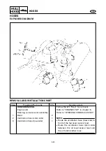
Check valve inspection

1. Check:

Check valve
Faulty 

 Replace.

Checking steps:

Connect a hose to the end of check
valve “A” and blow into it.
Air should come out from end “B”.

Connect the hose to the end of check
valve “B” and blow into it.
Air should not come out from end “A”.

Ventilation hose installation

1. Install:

Ventilation hose

NOTE:

Insert the ventilation hose into the ventila-
tion fitting until it reaches the bend 

a

 in the

fitting.

a

a

Summary of Contents for WaveRunner GP1200R

Page 1: ...LIT186160215 SERVICE MANUAL LIT 18616 02 15 F0X 28197 ZA 11 WaveRunnerGP1200R...

Page 2: ...ay differ in detail from the descriptions and illustrations given in this publica tion Use only the latest edition of this manual Authorized Yamaha dealers are notified periodically of modifications a...

Page 3: ...evised format the condition of a faulty component will precede an arrow symbol and the course of action required will follow the symbol e g Bearings Pitting scratches Replace To assist you in finding...

Page 4: ...follow WARNING instructions could result in severe injury or deathto the machine operator a bystander or a person inspecting or repairing the water vehicle CAUTION A CAUTION indicates special precauti...

Page 5: ...indicate parts to be lubricated or replaced see SYMBOLS 4 A job instruction chart accompanies the exploded diagram providing the order of jobs names of parts notes in jobs etc 5 Dimension figures and...

Page 6: ...te the grade of lubricant and the loca tion of lubrication point F Apply YAMALUBE 2 W oil G Apply water resistant grease Yamaha grease A Yamaha marine grease H Apply molybdenum disulfide grease Symbol...

Page 7: ...SPECIFICATIONS 2 SPEC PERIODIC INSPECTION AND ADJUSTMENT 3 FUEL SYSTEM 4 FUEL POWER UNIT 5 POWR JET PUMP UNIT 6 JET PUMP ELECTRICAL SYSTEM 7 ELEC HULL AND HOOD 8 HULL HOOD TROUBLE ANALYSIS 9 GEN INFO...

Page 8: ...BER 1 1 JET PUMP UNIT SERIAL NUMBER 1 1 HULL IDENTIFICATION NUMBER H l N 1 1 SAFETY WHILE WORKING 1 2 FIRE PREVENTION 1 2 VENTILATION 1 2 SELF PROTECTION 1 2 OILS GREASES AND SEALING FLUIDS 1 2 GOOD W...

Page 9: ...y l D number F0X 800101 ENGINE SERIAL NUMBER The engine serial number is stamped on a label attached to the cylinder head Starting serial number 67X 000101 JET PUMP UNIT SERIAL NUMBER The jet pump uni...

Page 10: ...Petroleum vapor is heavier than air and is deadly if inhaled in large quantities Engine exhaust gases are harmful to breathe When test running an engine indoors maintain good ventilation SELF PROTECT...

Page 11: ...iled rag in your pocket 4 Hands and any other part of the body which have been in contact with lubri cants or lubricant contaminated cloth ing should be thoroughly washed with hot water and soap as so...

Page 12: ...ling 2 Oil the contact surfaces of moving parts during assembly 3 After assembly check that moving parts operate normally 4 Install bearings with the manufacturer s markings on the side exposed to vie...

Page 13: ...06760 2 Dial gauge and stand P N YU 03097 YU 01256 90890 01252 3 Pocket tester P N YU 03112 90890 03112 4 Cylinder gauge set P N YU 03017 90890 06759 5 Compression gauge P N YU 33223 90890 03160 6 Di...

Page 14: ...bearing attachment jet pump bearing and oil seal P N YB 06112 YB 06196 90890 06614 90890 06653 12 Ball bearing attachment jet pump oil seal P N YB 06156 90890 06634 13 Driver rod intermediate shaft an...

Page 15: ...IFICATIONS GENERAL SPECIFICATIONS 2 1 MAINTENANCE SPECIFICATIONS 2 3 ENGINE 2 3 JET PUMP UNIT 2 4 HULL AND HOOD 2 4 ELECTRICAL 2 5 TIGHTENING TORQUES 2 7 SPECIFIED TORQUES 2 7 GENERAL TORQUE 2 10 CABL...

Page 16: ...ratio 5 9 1 Intake system Reed valve Carburetor model manufacturer quantity BN44 MIKUNI 3 Enrichment control Choke valve Scavenging system Loop charge Lubrication system Variable oil injection Cooling...

Page 17: ...E 2 W oil Using another oil can seriously damage the catalytic converter and other engine components FUEL AND OIL Fuel Regular unleaded gasoline Minimum fuel rating PON 86 RON 90 Oil YAMALUBE 2 W Fuel...

Page 18: ...3 1462 Measuring point mm in 22 0 87 Piston to cylinder clearance mm in 0 100 0 105 0 0039 0 0041 Wear limit mm in Cylinder bore 0 105 0 0041 Piston pin bore inside diameter mm in 22 004 22 025 0 866...

Page 19: ...le valve 150 Valve seat size mm in 1 2 0 05 Trolling speed r min 1 350 50 REED VALVES Thickness mm in 0 6 0 024 Reed valve stopper height mm in 10 4 11 0 0 41 0 43 Reed valve warpage limit mm in 0 2 0...

Page 20: ...cranking 2 V 2 8 2 000 r min V 7 9 3 500 r min V 11 Lighting coil G G Output peak voltage lower limit cranking 1 V 9 cranking 2 V 9 2 000 r min V 14 3 500 r min V 14 Pickup coil resistance color 445...

Page 21: ...unloaded cranking V 7 2 000 r min V 12 6 3 500 r min V 12 6 STARTER MOTOR Brush length mm in 12 5 0 49 Wear limit mm in 6 5 0 26 Commutator undercut mm in 0 7 0 03 Limit mm in 0 2 0 01 Commutator diam...

Page 22: ...haust chamber joint exhaust manifold Bolt M10 4 39 3 9 28 271 LT Exhaust chamber stay bracket Bolt M10 2 39 3 9 28 271 LT Exhaust chamber stay cylinder head cylinder 1st Bolt M8 2 15 1 5 11 2nd 35 3 5...

Page 23: ...12 572 LT Intake grate hull Bolt M6 4 7 0 7 5 1 572 LT Nozzle ring nozzle Bolt M8 2 15 1 5 11 271 LT Nozzle deflector nozzle ring Bolt M8 2 15 1 5 11 271 LT Strainer cover impeller duct Bolt M6 4 7 0...

Page 24: ...ering console cover assembly deck Nut 2 5 0 5 3 6 Bolt M6 4 3 0 3 2 2 Screw M5 2 2 0 2 1 4 Nut M8 2 16 1 6 11 Multifunction meter holder Nut 2 2 0 2 1 4 Steering console cover side cover Screw M6 4 3...

Page 25: ...ch Tightening torque specifica tions for special components or assemblies are provided in applicable sections of this manual To avoid warpage tighten multi fastener assemblies in a crisscross fashion...

Page 26: ...6 7 8 9 0 1 2 2 3 2 4 5 6 7 1 Fuel filter 2 Fuel breather hose 3 Fuel hose 4 Pilot water hose 5 Bilge hose 6 Speed sensor lead 7 Electrical box lead 8 Starter motor lead 9 Generator lead 0 Battery neg...

Page 27: ...e 3 Cooling water hose 4 QSTS cable 5 Speed sensor lead 6 Bilge hose 7 Flushing hose 8 Electrical box 9 To stator assembly 0 To water temperature sensor A To cylinder 1 B To cylinder 2 C To cylinder 3...

Page 28: ...and adjustment 3 4 QSTS cable inspection and adjustment 3 5 YPVS cable adjustment 3 6 FUEL SYSTEM 3 7 Fuel line inspection 3 7 Trolling speed check and adjustment 3 8 OIL INJECTION SYSTEM 3 9 Oil line...

Page 29: ...ottle cable Inspect adjust 3 3 Carburetor throttle shaft Inspect adjust Choke cable Inspect adjust 3 4 QSTS cable Inspect adjust 3 5 YPVS cable Inspect adjust 3 6 FUEL SYSTEM Fuel tank Clean 4 9 Fuel...

Page 30: ...k and forth Check the excessive play of the han dlebar Inspection steps Turn the handlebar from lock to lock Measure distances a and b If the difference is not within specifica tion adjust the cable j...

Page 31: ...le lever free play adjust the trolling speed 1 Measure Throttle lever free play a Out of specification Adjust 2 Adjust Throttle lever free play WARNING The cable joint must be screwed in more than 8 m...

Page 32: ...en it is fully opened Check that the inner cable has some slack when the choke lever is com pletely closed Adjustment steps Loosen the locknut 1 Screw the adjuster 2 fully into the bracket Align the c...

Page 33: ...djust QSTS cable Adjustment steps Set the control grip in the neutral posi tion Loosen the locknut 1 Remove the nut 2 and pivot pin 3 Set the jet nozzle in the center posi tion Turn the cable joint 4...

Page 34: ...tment 1 Check YPVS valve position Incorrect position Adjust the YPVS cable Checking steps Start the engine and then stop it NOTE When the engine has been stopped for 3 seconds the YPVS valve assembly...

Page 35: ...oses through part Fuel filler cap Cracks damage Replace Adjustment steps Loosen locknuts 1 and 2 Turn in the adjuster 3 and 4 until there is slack in the cable Align the hole a in the pulley with the...

Page 36: ...n the water Start the engine and allow it to warm up for several minutes Attach the engine tachometer to the spark plug lead Engine tachometer YU 8036 A 90890 06760 Measure the engine trolling speed 2...

Page 37: ...2 Distinctly different color Check the engine condition 2 Clean Spark plug with a spark plug cleaner or wire brush Color guide Medium to light tan color Normal Whitish color Lean fuel mixture Air leak...

Page 38: ...of a turn b T R Spark plug 25 Nm 2 5 m kgf 18 ft lb ELECTRICAL Battery inspection WARNING Battery electrolyte is dangerous it contains sulfuric acid which is poisonous and highly caustic Always follow...

Page 39: ...batteries KEEP BATTERIES AND ELECTROLYTE OUT OF REACH OF CHILDREN CAUTION Do not place the battery on its side Before adding electrolyte or recharging be sure to remove the battery from the battery b...

Page 40: ...stilled water When the electrolyte level reaches the upper level mark allow the cell to stand for 20 minutes If the electrolyte level drops add more distilled water so the level reaches the upper leve...

Page 41: ...he terminals with a water resistant grease to minimize terminal corrosion 3 1 2 JET PUMP UNIT Impeller inspection 1 Check Impeller 1 Damage wear Replace Nicks scratches File or grind 2 Measure Impelle...

Page 42: ...he water inlet strainer mesh a Install the water inlet cover 1 a Bilge strainer inspection 1 Inspect Bilge strainer Contaminants Clean Cracks damage Replace Inspection steps Disconnect the bilge strai...

Page 43: ...ubricant Rust inhibitor 2 Lubricate QSTS control cables handlebar side NOTE Before lubricating the QSTS control cables remove the QSTS cable housing cover Spray the rust inhibitor into the outer cable...

Page 44: ...ble QSTS cables pulley side YPVS cables Recommended grease Yamaha marine grease Yamaha grease A Water resistant grease 5 Lubricate Nozzle pivot shaft Steering cable nozzle side QSTS cable nozzle side...

Page 45: ...ly a small amount of grease Recommended grease Yamaha marine grease Yamaha grease A Water resistant grease 7 Fill Intermediate housing NOTE Fill the intermediate housing with the rec ommended grease t...

Page 46: ...UEL TANK 4 6 EXPLODED DIAGRAM 4 6 REMOVAL AND INSTALLATION CHART 4 6 SERVICE POINTS 4 9 Check valve inspection 4 9 Fuel level switch inspection 4 9 Fuel tank inspection 4 9 Pipe joint inspection 4 9 I...

Page 47: ...et and carburetor body inspection 4 22 Carburetor assembly 4 22 FUEL PUMP 4 23 EXPLODED DIAGRAM 4 23 REMOVAL AND INSTALLATION CHART 4 23 SERVICE POINTS 4 25 Fuel pump inspection 4 25 Fuel filter inspe...

Page 48: ...AL AND INSTALLATION CHART Step Procedure Part name Q ty Service points FUEL COCK AND FUEL FILTER REMOVAL Follow the left Step for removal 1 Screw 1 2 Knob 1 3 Nut 1 4 Fuel cock assembly 1 5 Fuel hose...

Page 49: ...4 2 FUEL E FUEL COCK AND FUEL FILTER SERVICE POINTS Fuel filter inspection Refer to FUEL SYSTEM in chapter 3 Fuel cock inspection 1 Check Fuel cock Contaminants Clean Rough movement Replace...

Page 50: ...ure Part name Q ty Service points OIL TANK REMOVAL Follow the left Step for removal Engine unit Refer to ENGINE UNIT in chapter 5 Steering console cover assembly Refer to STEERING CONSOLE COVER in cha...

Page 51: ...IAGRAM Step Procedure Part name Q ty Service points 6 Breather hose 1 7 Oil hose 1 8 Bolt 2 9 Tank belt 2 10 Oil tank assembly 1 11 Hose clamp 1 12 Oil filler hose 1 13 Oil level sensor 1 Reverse the...

Page 52: ...minants Clean Frays tears Replace Rubber seal Cracks wear Replace Oil hose Oil tank Oil filler cap Cracks damage Replace Check valve Malfunction Replace Oil level switch inspection Refer to INDICATION...

Page 53: ...ND INSTALLATION CHART Step Procedure Part name Q ty Service points FUEL TANK REMOVAL Follow the left Step for removal Oil tank Refer to OIL TANK 1 Fuel level sensor coupler 1 2 Hose clamp 1 3 Nut 1 4...

Page 54: ...D DIAGRAM Step Procedure Part name Q ty Service points 7 Fuel hose 1 8 Fuel return hose 1 Red mark a 9 Fuel breather hose 1 10 Fuel tank assembly 1 11 Hose clamp 1 12 Fuel filler hose 1 13 Hose clamp...

Page 55: ...ODED DIAGRAM Step Procedure Part name Q ty Service points 15 One way valve 1 16 Screw washer 1 1 17 Filter 1 18 Screw washer 1 1 19 Sleeve 1 20 Floatation 1 21 Bolt 2 22 Tank bolt 2 Reverse the remova...

Page 56: ...ter 7 Fuel tank inspection 1 Inspect Fuel tank Cracks damage Replace Pipe joint inspection 1 Inspect Pipe Contaminants Clean Bends damage Replace Checking steps Connect a hose to the end of check valv...

Page 57: ...y Service points INTAKE DUCT AND SILENCER REMOVAL Follow the left Step for removal Exhaust chamber assembly Refer to EXHAUST CHAMBER ASSEMBLY in chapter 5 1 Hose clamp 1 2 Silencer 1 3 Hose clamp 2 4...

Page 58: ...NCER EXPLODED DIAGRAM Step Procedure Part name Q ty Service points 6 Bolt collar grommet 1 1 1 7 Intake duct 1 8 Silencer case 1 9 Bolt 6 10 Spark arrester 1 11 Silencer plate 1 12 O ring 3 Reverse th...

Page 59: ...ervice points CARBURETOR UNIT REMOVAL Follow the left Step for removal Silencer plate Refer to INTAKE DUCT AND SILENCER 1 Oil pump cable 1 NOTE Before removing the oil pump cable mark the cable s inst...

Page 60: ...Part name Q ty Service points 5 Fuel return hose 1 Red mark a 6 Oil delivery hose 3 7 Clamp fuel pump vacuum hose 3 3 8 Remote throttle stop screw 1 9 Bolt 6 10 Bolt 4 11 Carburetor assembly 1 12 Gask...

Page 61: ...ALLATION CHART Step Procedure Part name Q ty Service points CARBURETOR UNIT SEPARATION Follow the left Step for removal 1 Hose 2 Fuel suction 2 Hose 2 Fuel return 3 Accelerator pump hose 1 4 Remote th...

Page 62: ...E CARBURETOR UNIT EXPLODED DIAGRAM Step Procedure Part name Q ty Service points 7 Bolt 3 8 Cable holder 1 9 Bolt 6 10 Carburetor 3 11 Gasket 3 12 Plate 1 Reverse the removal steps for installation Not...

Page 63: ...ew end from the throttle lever Check the each throttle valve is fully closed 2 Adjust Throttle valve synchronization Adjustment steps Loosen the remote throttle stop screw 1 until untouched the screw...

Page 64: ...installation position a 16 18 mm 0 63 0 71 in Throttle cable guide installation position b 18 20 mm 0 71 0 79 in 2 Adjust Throttle lever free play Refer to CONTROL SYSTEM in chapter 3 Oil pump cable i...

Page 65: ...ty Service points CARBURETOR DISASSEMBLY Follow the left Step for disassembly 1 Accelerator pump delivery hose 2 For carburetor 3 2 Accelerator pump fuel hose 1 3 Screw 4 4 Accelerator pump carburetor...

Page 66: ...tep Procedure Part name Q ty Service points 10 Pilot jet 1 11 Screw 1 12 Arm 1 13 Arm pin 1 14 Spring 1 15 Screw 1 16 Needle valve seat holder 1 17 Needle valve 1 18 Needle valve seat 1 19 O ring 1 Re...

Page 67: ...e Part name Q ty Service points ACCELERATOR PUMP DISASSEMBLY Follow the left Step for disassembly 1 Screw 1 2 Stay 1 3 Spring 1 4 Spring seat 1 5 Screw 4 6 Accelerator pump cover assembly 1 7 Spring 1...

Page 68: ...ator pump body inspection 1 Inspect One way valve Crack damage Replace the acceler ator pump body Fuel passage Clog Clean or replace Arm inspection 1 Inspect Arm 1 Bends damage Repair or replace 2 Mea...

Page 69: ...n Wear b Replace NOTE Always replace the needle valve and needle valve seat as a set Jet and carburetor body inspection 1 Inspect Main jet Pilot jet Carburetor body Clog contaminants Clean Damage wear...

Page 70: ...AND INSTALLATION CHART Step Procedure Part name Q ty Service points FUEL PUMP DISASSEMBLY Follow the left Step for disassembly Carburetors Refer to CARBURETOR 1 Screw 4 2 Fuel pump cover 1 3 Gasket 1...

Page 71: ...4 24 FUEL E FUEL PUMP EXPLODED DIAGRAM Step Procedure Part name Q ty Service points 7 Rubber diaphragm 1 8 Diaphragm 1 9 Packing 1 10 Fuel filter 1 Reverse the disassembly steps for assembly...

Page 72: ...FUEL E FUEL PUMP SERVICE POINTS Fuel pump inspection 1 Inspect Diaphragm Rubber diaphragm Diaphragm body Damage Replace Fuel filter inspection 1 Inspect Fuel filter Clog contaminants Clean Damage Rep...

Page 73: ...Part name Q ty Service points OIL PUMP REMOVAL Follow the left Step for removal Engine unit Refer to ENGINE UNIT in chapter 5 1 Bolt 1 2 Bleed hose stay 1 3 Bolt 2 4 Oil pump assembly 1 5 Gasket 1 6 O...

Page 74: ...rt name Q ty Service points OIL PUMP HOSES AND CABLE REMOVAL Follow the left Step for removal 1 Bleed hose 1 2 Air bleed screw 1 3 Gasket 1 4 Bleed hose stay 1 5 Oil delivery hose 1 3 6 Oil delivery h...

Page 75: ...Replace CAUTION If the oil delivery hoses are not full of oil fill them up After installing the oil injection system bleed the system of any air Check valve inspection 1 Check Check valve Faulty Repl...

Page 76: ...ump cable NOTE If the installation position has been marked for reference on the inner cable at the car buretor end while marks a and b are aligned adjusting the cable at the carbure tor end is easier...

Page 77: ...ith a locking tie Recommended engine oil YAMALUBE 2 W oil only Loosen the air bleed screw 1 two full turns and make sure that both the oil and air bubbles flow out When there are no air bubbles left t...

Page 78: ...13 Engine mount inspection 5 13 Coupling clearance inspection 5 13 EXHAUST MANIFOLD 5 14 EXPLODED DIAGRAM 5 14 REMOVAL AND INSTALLATION CHART 5 14 REED VALVES 5 16 EXPLODED DIAGRAM 5 16 REMOVAL AND I...

Page 79: ...on 5 31 GENERATOR AND STARTER MOTOR 5 33 EXPLODED DIAGRAM 5 33 REMOVAL AND INSTALLATION CHART 5 33 SERVICE POINTS 5 40 Drive coupling removal and installation 5 40 Flywheel magneto removal and install...

Page 80: ...HOSES AND LEADS REMOVAL Follow the left Step for removal YPVS servomotor Refer to YPVS SERVOMOTOR in chapter 7 Battery box Refer to BATTERY BOX in chapter 8 1 Spark plug cap 3 2 Exhaust temperature s...

Page 81: ...LODED DIAGRAM Step Procedure Part name Q ty Service points 4 AC magneto coupler 1 5 Cap bolt 3 3 6 Cover 1 7 Water hose clamp 2 2 For cooling water pilot outlet on port side 6 22 mm 12 Nm 1 2 m kgf 8...

Page 82: ...ose clamp 2 Slide the outer exhaust joint 9 Hose clamp 2 10 Hose clamp 1 11 Water lock band 1 Slide the water lock 12 Bolt 4 13 Intermediate housing grease hose 1 14 Nut 2 15 Eye 2 NOTE Remove the spa...

Page 83: ...ty Service points 16 Bolt 2 17 Bolt 1 18 Bolt 1 19 Bolt 1 20 Muffler stay 2 1 21 Muffler assembly 1 NOTE Remove the cylinder head if it is difficult to remove the muffler assembly 22 Outer exhaust joi...

Page 84: ...ATION CHART Step Procedure Part name Q ty Service points MUFFLER DISASSEMBLY Follow the left Step for disassembly 1 Exhaust temperature sensor 1 2 Water temperature sensor 1 3 Bolt 2 4 Muffler stay 1...

Page 85: ...D DIAGRAM Step Procedure Part name Q ty Service points 9 Gasket 1 10 Catalyst 1 11 Gasket 1 12 Pin 2 13 Bolt 6 14 Mixing joint 1 15 Gasket 1 16 Muffler 1 Reverse the disassembly steps for assembly Not...

Page 86: ...5 7 POWR E MUFFLER ASSEMBLY SERVICE POINT Catalyst inspection 1 Inspect Catalyst Cracks damage Replace...

Page 87: ...CHART Step Procedure Part name Q ty Service points EXHAUST CHAMBER ASSEMBLY REMOVAL Follow the left Step for removal Muffler assembly Refer to MUFFLER ASSEMBLY 1 Clamp hose 3 3 For cooling water pilot...

Page 88: ...ervice points 8 Exhaust chamber assembly 1 NOTE Before installing the exhaust chamber assembly install the clamp hose step No 7 and place the bolts step No 2 in the bolts holes of the exhaust chamber...

Page 89: ...NSTALLATION CHART Step Procedure Part name Q ty Service points EXHAUST CHAMBER DISASSEMBLY Follow the left Step for disassembly 1 Bolt 5 2 Bolt 1 3 Exhaust chamber joint 1 4 Gasket 1 5 Pin 2 6 Exhaust...

Page 90: ...ENGINE UNIT REMOVAL Follow the left Step for removal Carburetor unit Refer to CARBURETOR UNIT in chapter 4 1 Clamp water hose 1 1 Should be white mark a up side 2 Oil suction hose 1 3 Oil return hose...

Page 91: ...rt name Q ty Service points 6 Coupling cover 1 7 Bolt washer 4 4 8 Engine assembly 1 9 Shim Install the shims original position Reverse the removal steps for installation As required LT 572 LT 572 8 4...

Page 92: ...pection 1 Inspect Engine mounts Cracks damage Replace Coupling clearance inspection 1 Measure Clearance a Clearance b with the rubber damper Out of specification Adjust NOTE Measure the clearances wit...

Page 93: ...LATION CHART Step Procedure Part name Q ty Service points EXHAUST MANIFOLD AND LEADS REMOVAL Follow the left Step for removal Engine unit Refer to ENGINE UNIT 1 Bolt 4 2 Bolt 6 3 Nut 2 4 Exhaust manif...

Page 94: ...L AND INSTALLATION CHART Step Procedure Part name Q ty Service points EXHAUST MANIFOLD DISASSEMBLY Follow the left Step for disassembly 1 Clamp hose 1 1 2 Bolt 6 3 Water pipe 1 4 O ring 3 5 Exhaust ma...

Page 95: ...rvice points REED VALVE REMOVAL Follow the left Step for removal Carburetor unit Refer to CARBURETOR UNIT in chapter 4 1 Bolt 18 NOTE Tighten the bolts in the proper sequence as shown 2 Reed valve pla...

Page 96: ...tion 1 Inspect Reed valves Cracks damage Replace 2 Measure Valve bending a Out of specification Replace 3 Measure Valve stopper height b Out of specification Adjust or replace Max valve bending 0 2 mm...

Page 97: ...RT Step Procedure Part name Q ty Service points YPVS REMOVAL Follow the left Step for removal Exhaust chamber assembly Refer to EXHAUST CHAMBER ASSEMBLY 1 Bolt 12 2 YPVS valve cover 3 3 Gasket 3 4 Spa...

Page 98: ...S EXPLODED DIAGRAM Step Procedure Part name Q ty Service points 7 Washer 5 8 Bolt 3 NOTE During installation align the hole a in the YPVS shaft with the bolt 9 Shaft 3 1 10 Shaft 2 1 11 Shaft 1 1 12 Y...

Page 99: ...EXPLODED DIAGRAM Step Procedure Part name Q ty Service points 13 Bolt 3 14 YPVS valve assembly 3 15 Oil seal 6 NOTE If the YPVS shaft is removed the oil seal must be replaced Reverse the removal steps...

Page 100: ...arbon deposits with a rounded scraper 1 CAUTION Do not use a sharp instrument to avoid damaging or scratching the surfaces 2 Inspect YPVS valve assembly Crack damage wear Replace YPVS valve installati...

Page 101: ...t name Q ty Service points CYLINDER HEAD REMOVAL Follow the left Step for removal Exhaust chamber assembly Refer to EXHAUST CHAMBER ASSEMBLY 1 Spark plug 3 2 Bolt 1 NOTE Tighten the bolts in the prope...

Page 102: ...EXPLODED DIAGRAM Step Procedure Part name Q ty Service points 7 Cylinder head cover 1 8 Gasket 1 9 Cylinder head 1 10 Gasket 1 11 Clamp hose 2 2 a white mark Reverse the removal steps for installation...

Page 103: ...ylinder head or spark plug bore threads 2 Inspect Cylinder head water jacket Corrosion mineral deposits Clean or replace 3 Measure Cylinder head warpage with a straightedge and thickness gauge Out of...

Page 104: ...oints CYLINDER REMOVAL Follow the left Step for removal YPVS Refer to YPVS Cylinder head Refer to CYLINDER HEAD 1 Bolt 12 NOTE Tighten the bolts in a crisscross pattern and in two stages 2 Cylinder 3...

Page 105: ...D with a cylinder gauge Out of specification Replace cylin der and piston as a set NOTE Measure the cylinder bore in parallel and at a right angle to the crankshaft Then aver age the measurements Stan...

Page 106: ...name Q ty Service points PISTON REMOVAL Follow the left Step for removal Cylinders Refer to CYLINDERS 1 Piston pin clip 2 CAUTION Do not align the open end of the clip with the piston pin slot a 2 Pi...

Page 107: ...OWR E PISTONS EXPLODED DIAGRAM Step Procedure Part name Q ty Service points 5 Bearing 1 6 Piston ring 2 CAUTION Align each end gap with its respective locating pin Reverse the removal steps for instal...

Page 108: ...ton pin clip from falling into the crankcase Piston inspection 1 Eliminate Carbon deposits from the piston crown and piston ring gloves 2 Inspect Piston wall Score marks Repair with 600 800 grit wet s...

Page 109: ...s NOTE New cylinder bore size 80 000 a 1 000 Example a 12 80 012 mm PISTON CLEARANCE CYLINDER BORE PISTON DIAMETER Piston to cylinder clearance 0 100 0 105 mm 0 0039 0 0041 in Cylinder size indication...

Page 110: ...in Piston pin and bearing inspection 1 Inspect Piston pins Bearings Signs of heat discoloration Replace 2 Measure Piston pin outside diameter with a micrometer 1 Out of specification Replace Piston pi...

Page 111: ...2 POWR E PISTONS 4 Check Piston pin to connecting rod free play with the piston pin in the small end of the connecting rod as shown Free play small end wear Replace the piston pin connecting rod or bo...

Page 112: ...MOTOR EXPLODED DIAGRAM REMOVAL AND INSTALLATION CHART Step Procedure Part name Q ty Service points GENERATOR COVER REMOVAL Follow the left Step for removal Oil pump Refer to OIL PUMP in chapter 4 1 B...

Page 113: ...POWR E GENERATOR AND STARTER MOTOR EXPLODED DIAGRAM Step Procedure Part name Q ty Service points 6 Spring 1 7 Packing 1 8 Pin 2 9 Bolt 2 10 Bolt 2 11 Bracket 1 Reverse the removal steps for installat...

Page 114: ...MOVAL Follow the left Step for removal 1 Bolt 3 NOTE This washer holds the pickup coil lead Make sure to not pinch the lead between the projection and the washer when installing the bolt 2 Washer 1 3...

Page 115: ...TION CHART Step Procedure Part name Q ty Service points GENERATOR ROTOR AND STARTER MOTOR REMOVAL Follow the left Step for removal 1 Drive coupling 1 2 Flywheel magneto bolt 1 3 Flywheel magneto 1 4 W...

Page 116: ...37 POWR E GENERATOR AND STARTER MOTOR EXPLODED DIAGRAM Step Procedure Part name Q ty Service points 8 Nut washer 1 1 9 Starter motor lead 1 10 Starter motor 1 Reverse the removal steps for installatio...

Page 117: ...DIAGRAM REMOVAL AND INSTALLATION CHART Step Procedure Part name Q ty Service points STARTER CLUTCH DISASSEMBLY Follow the left Step for disassembly 1 Clip 1 2 Clip stopper 1 3 Spring seat 1 4 Spring 1...

Page 118: ...5 39 POWR E GENERATOR AND STARTER MOTOR EXPLODED DIAGRAM Step Procedure Part name Q ty Service points 8 Weight 3 9 Spring ring 1 10 Pinion gear 1 Reverse the disassembly steps for assembly...

Page 119: ...al and installation 1 Remove Flywheel magneto bolt NOTE Install the bolt with the same special tool that was used for removal 2 Remove Generator rotor For USA and Canada For worldwide CAUTION To preve...

Page 120: ...Inspect Drive coupling Damage wear Replace Flywheel magneto inspection 1 Inspect Ring gear Damage wear Replace Starter clutch assembly inspection 1 Inspect Pinion gear 1 Idle gear 2 Damage wear Replac...

Page 121: ...ON CHART Step Procedure Part name Q ty Service points CRANKCASE DISASSEMBLY Follow the left Step for disassembly Pistons Refer to PISTONS Generator cover and starter motor Refer to GENERATOR AND START...

Page 122: ...IAGRAM Step Procedure Part name Q ty Service points 7 Bolt 1 NOTE Tighten the bolts in sequence as shown 8 Bolt 16 9 Lower crankcase 1 10 Pin 2 11 Crankshaft assembly 1 12 Upper crankcase 1 Reverse th...

Page 123: ...crankcase Crankcase Cracks damage Replace Crankcase installation 1 Apply Gasket Maker onto the crankcase mating surfaces NOTE Before applying Gasket Maker clean the crankcase mating surfaces 2 Check...

Page 124: ...Part name Q ty Service points CRANKSHAFT REMOVAL Follow the left Step for removal Crankcase Refer to CRANKCASE 1 Oil seal 1 2 Bearing 1 3 Oil seal 2 4 Crankshaft assembly 1 CAUTION Install the bearin...

Page 125: ...Deflection B with a dial gauge Out of specification Replace Max deflection B 0 05 mm 0 002 in C 0 15 mm 0 006 in 3 Measure Big end side clearance D with a thickness gauge Out of specification Replace...

Page 126: ...RANKSHAFT 5 Inspect Bearings Damage pitting Replace NOTE Before inspection thoroughly clean the bearings Immediately after inspection lubricate the bearings to prevent rust 6 Inspect Oil seals Damage...

Page 127: ...9 Impeller inspection 6 10 Drive shaft inspection 6 10 Drive shaft installation 6 10 TRANSOM PLATE AND HOSES 6 13 EXPLODED DIAGRAM 6 13 REMOVAL AND INSTALLATION CHART 6 13 SERVICE POINTS 6 15 Bilge s...

Page 128: ...LATION CHART Step Procedure Part name Q ty Service points JET PUMP UNIT REMOVAL Follow the left Step for removal 1 Bolt 2 2 Bolt 2 3 Intake grate 1 4 Bolt 4 5 Intake duct 1 6 Screw 4 7 Speed sensor 1...

Page 129: ...UMP UNIT EXPLODED DIAGRAM Step Procedure Part name Q ty Service points 8 Bolt 4 9 Ride plate 1 10 QSTS cable joint 1 11 Bilge hose 1 12 Nut washer 1 2 13 Steering cable joint 1 14 Clamp spout hose 1 1...

Page 130: ...ame Q ty Service points 17 Jet pump unit assembly 1 NOTE Pull the jet pump unit straight back When installing the jet pump unit align the drive shaft spline male with the intermediate drive shaft spli...

Page 131: ...VAL AND INSTALLATION CHART Step Procedure Part name Q ty Service points NOZZLE DEFLECTOR AND NOZZLE RING REMOVAL Follow the left Step for removal Jet pump unit Refer to JET PUMP UNIT 1 Bolt 2 2 Collar...

Page 132: ...TALLATION CHART Step Procedure Part name Q ty Service points IMPELLER DUCT AND IMPELLER HOUSING REMOVAL Follow the left Step for removal Nozzle ring Refer to NOZZLE DEFLECTOR AND NOZZLE RING 1 Bolt 4...

Page 133: ...DUCT IMPELLER HOUSING AND INTAKE DUCT EXPLODED DIAGRAM Step Procedure Part name Q ty Service points 7 Bolt 4 8 Water inlet cover 1 9 Packing 1 10 Water inlet strainer 1 11 Packing 1 Reverse the remova...

Page 134: ...LODED DIAGRAM REMOVAL AND INSTALLATION CHART 1 EPNOC grease AP 0 Step Procedure Part name Q ty Service points IMPELLER DUCT AND DRIVE SHAFT DISASSEMBLY Follow the left Step for disassembly 1 Impeller...

Page 135: ...GRAM 1 EPNOC grease AP 0 Step Procedure Part name Q ty Service points 8 Drive shaft 1 9 Rear bearing 1 10 Spacer 1 11 Front bearing 1 12 Oil seal 1 13 Oil seal 1 Reverse the disassembly steps for asse...

Page 136: ...sen it 2 Remove Nut 1 Drive shaft holder YB 06151 90890 06519 Drive shaft holder YB 06151 90890 06519 3 Remove Drive shaft 1 NOTE Remove the drive shaft with a press 4 Remove Rear bearing For USA and...

Page 137: ...Refer to JET PUMP UNIT in chapter 3 Drive shaft inspection 1 Inspect Drive shaft Damage wear Replace Driver rod L3 YB 06071 90890 06652 Needle bearing attachment YB 06112 90890 06614 Driver rod L3 YB...

Page 138: ...socket 4 Add EPNOC grease AP 0 between the drive shaft and spacer Distance a 23 0 1 mm 0 91 0 004 in Quantity Approximately 1 3 of capacity a 5 Install Rear bearing NOTE Press the bearing inner outer...

Page 139: ...6 12 E JET PUMP IMPELLER DUCT AND DRIVE SHAFT 6 Add EPNOC grease AP 0 into the cap Quantity Approximately 1 3 of capacity 7 Install Nut Impeller Drive shaft holder YB 06151 90890 06519...

Page 140: ...ep Procedure Part name Q ty Service points TRANSOM PLATE AND HOSES REMOVAL Follow the left Step for removal Exhaust system Refer to EXHAUST SYSTEM in chapter 8 Jet pump unit Refer to JET PUMP UNIT 1 H...

Page 141: ...DED DIAGRAM Step Procedure Part name Q ty Service points 4 Hose 1 Cooling water inlet 5 Nut washer 4 4 6 Transom plate 1 7 Clamp bilge hose 2 1 1 8 Screw 1 9 Bilge strainer holder 1 10 Bilge strainer...

Page 142: ...6 15 E JET PUMP TRANSOM PLATE AND HOSES SERVICE POINTS Bilge strainer inspection Refer to JET PUMP UNIT in chapter 3 Bilge hose inspection 1 Inspect Bilge hose Cracks damage wear Replace...

Page 143: ...t name Q ty Service points BEARING HOUSING REMOVAL Follow the left Step for removal Engine unit Refer to ENGINE UNIT in chapter 5 1 Rubber coupling 1 2 Bolt 3 3 Intermediate housing assembly 1 4 Pin 2...

Page 144: ...D INSTALLATION CHART Step Procedure Part name Q ty Service points BEARING HOUSING DISASSEMBLY Follow the left Step for disassembly 1 Grease hose 1 2 Grease nipple 1 3 Grease nipple stay 1 4 Nipple 2 5...

Page 145: ...DIAGRAM Step Procedure Part name Q ty Service points 8 O ring 2 9 Oil seal 1 10 Oil seal 1 11 Oil seal 1 12 Circlip 1 13 Bearing 1 14 Circlip 1 Reverse the disassembly steps for assembly Not reusable...

Page 146: ...en cou pling shaft Bearing removal 1 Remove Bearing NOTE Install the bearing with the same special tools that were used for removal Support the intermediate housing with steel blocks 1 and press the b...

Page 147: ...ction 1 Inspect Driven coupling Driven coupling damper Damage wear Replace Bearing installation 1 Install Circlip rear 2 Install Bearing Oil seal installation 1 Install Oil seal NOTE Before installing...

Page 148: ...Distance b 1 6 2 0 mm 0 06 0 08 in Intermediate housing installation 1 Install Intermediate housing Shim NOTE Install the shim s to the original position if the intermediate housing is not replaced I...

Page 149: ...TION SPARK GAP 7 11 IGNITION SYSTEM PEAK VOLTAGE 7 12 BATTERY 7 14 FUSE 7 14 SPARK PLUGS 7 14 SPARK PLUG LEAD ASSEMBLY 7 14 IGNITION COIL 7 15 ENGINE STOP SWITCH 7 15 WATER TEMPERATURE SENSOR 7 16 EXH...

Page 150: ...installation 7 30 YPVS cable inspection 7 30 YPVS servomotor inspection 7 30 YPVS cable adjustment 7 31 INDICATION SYSTEM 7 32 WIRING DIAGRAM 7 32 FUSE 7 33 BATTERY 7 33 LIGHTING COIL 7 33 RECTIFIER...

Page 151: ...level sensor 3 Multi function meter 4 YPVS servomotor 5 Spark plugs 6 Exhaust temperature sensor 7 Electrical box 8 Speed sensor 9 Battery 0 Water temperature sensor A Starter motor B Stator coil and...

Page 152: ...name Q ty Service points ELECTRICAL BOX REMOVAL Follow the left Step for removal Engine unit Refer to ENGINE UNIT in chapter 5 Battery negative lead Starter motor lead Refer to GENERATOR AND STARTER M...

Page 153: ...art name Q ty Service points ELECTRICAL BOX DISASSEMBLY Follow the left Step for disassembly 1 Clamp 5 2 Coupler 3 For water exhaust temperature sensor and lighting coil 3 Screw 2 4 Rectifier regulato...

Page 154: ...name Q ty Service points 11 Ignition coil 3 12 Ignition coil lead 3 13 Spark plug lead cap 3 3 14 Bolt 3 15 Ground lead 6 16 Lead 3 Black orange 17 Nut 2 18 Starter motor lead 1 19 Battery positive le...

Page 155: ...ep Procedure Part name Q ty Service points 23 Lead holder 1 24 Fuse lead 5 25 Screw 2 26 Fuse holder 1 27 Lead coupler 1 6 28 Screw 2 29 Coupler bracket 1 30 CDI unit 1 31 Screw 8 32 Lead holder plate...

Page 156: ...ry positive terminal To starter motor Affix the ignition coil connector to the electrical box holder Pass the 8 pin coupler leads behind the CDI unit and insert them into the bracket Br Brown G Green...

Page 157: ...strument powered by dry batter ies check the battery s voltage periodi cally and replace the batteries if necessary Digital circuit tester NOTE Throughout this chapter the digital circuit tester s par...

Page 158: ...OTE When checking the condition of the igni tion system it is vital to know the peak voltage Cranking speed is dependant on many factors e g fouled or weak spark plugs a weak battery If one of these i...

Page 159: ...ollow ing tests Voltage measurement Peak voltage measurement Test harness NOTE Make sure the output lead red lead of the rectifier regulator is disconnected when measuring the peak voltage of the ligh...

Page 160: ...ne stop lanyard switch 3 Lighting coil 4 Pickup coil 5 CDI unit 6 Ignition coil 7 Spark plug 8 Fuse 20A 9 Battery 0 Rectifier regulator A Exhaust temperature sensor B Water temperature sensor B Black...

Page 161: ...p flammable gas or liquids away since this test can produce sparks 1 Check Ignition spark gap Below specification Check the CDI unit output peak voltage Check the ignition coil for resistance For USA...

Page 162: ...s obtained the problem is not with the ignition system but possibly with the spark plug s or another compo nent 1 Measure CDI unit output peak voltage Below specification Measure the rectifier regulat...

Page 163: ...tion Replace the lighting coil NOTE Make sure the output lead red lead of the rectifier regulator is disconnected when measuring the output peak voltage The starter motor will not operate when the tes...

Page 164: ...k voltage Rectifier regulator output peak voltage Red R Black B r min Unloaded Cranking 2 000 3 500 V 7 12 6 12 6 BATTERY Refer to ELECTRICAL in chapter 3 FUSE Refer to STARTING SYSTEM SPARK PLUGS Ref...

Page 165: ...ance measurement Primary coil resistance Black white B W Body 0 26 0 36 at 20 C 68 F 2 Measure Secondary coil resistance Out of specification Replace Secondary coil resistance Black white B W Spark pl...

Page 166: ...r temperature sen sor in a container filled with oil Slowly heat the oil Measure the resistance when the spec ified temperature is reached EXHAUST TEMPERATURE SENSOR 1 Measure Exhaust temperature sens...

Page 167: ...EC STARTING SYSTEM STARTING SYSTEM WIRING DIAGRAM 1 CDI unit 2 Engine stop lanyard switch 3 Starter switch 4 Fuse 10A 5 Fuse 20A 6 Starter relay 7 Starter motor 8 Battery B Black Br Brown R Red R Y Re...

Page 168: ...perly connect FUSE 1 Check Fuse holder continuity No continuity Check the fuse or replace the fuse holder Fuse holder continuity Between 1 and 2 Between 2 and 3 2 Check Fuse broken Broken Replace NOTE...

Page 169: ...d terminal Black lead terminal Loose Tighten 2 Check Starter relay Faulty Replace Checking steps Connect the tester leads between the starter relay terminals as shown Connect the brown lead terminal t...

Page 170: ...name Q ty Service points STARTER MOTOR DISASSEMBLY Follow the left Step for disassembly Starter motor Refer to GENERATOR AND STARTER MOTOR in chapter 5 1 O ring 1 2 Bolt 2 3 Starter motor front cover...

Page 171: ...name Q ty Service points 8 Starter motor rear cover 1 9 O ring 1 10 Shim t 0 2 mm 0 8 mm 11 Armature assembly 1 12 Nut spring washer washer 1 1 4 13 O ring 1 14 Brush holder 1 15 Brush spring 4 16 Bo...

Page 172: ...7 22 E ELEC STARTER MOTOR EXPLODED DIAGRAM Step Procedure Part name Q ty Service points 18 Spacer 1 19 Holder 1 20 Starter motor yoke 1 Reverse the disassembly steps for assembly...

Page 173: ...Clean with 600 grit sandpaper 3 Measure Commutator diameter Out of specification Replace Min commutator diameter 27 0 mm 1 06 in 4 Check Commutator undercut Contaminants Clean NOTE Remove all mica an...

Page 174: ...nt Armature shaft No continuity Brush holder inspection 1 Measure Brush length a Out of specification Replace Min brush length 6 5 mm 0 26 in 2 Check Brush holder continuity Out of specification Repla...

Page 175: ...7 25 E ELEC CHARGING SYSTEM CHARGING SYSTEM WIRING DIAGRAM 1 Lighting coil 2 Battery 3 Fuse 20A 4 Rectifier regulator B Black G Green R Red G W Green white...

Page 176: ...7 26 E ELEC CHARGING SYSTEM FUSE Refer to STARTING SYSTEM BATTERY Refer to ELECTRICAL in chapter 3 LIGHTING COIL Refer to IGNITION SYSTEM RECTIFIER REGULATOR Refer to IGNITION SYSTEM...

Page 177: ...S YPVS WIRING DIAGRAM 1 Lighting coil 2 Pickup coil 3 CDI unit 4 YPVS servomotor 5 Fuse 10A 6 Fuse 20A 7 Battery 8 Rectifier regulator B Black Gy Gray R Red B O Black orange R L Red blue R W Red white...

Page 178: ...Refer to STARTING SYSTEM BATTERY Refer to ELECTRICAL in chapter 3 PICKUP COIL Refer to IGNITION SYSTEM CDI UNIT Refer to IGNITION SYSTEM LIGHTING COIL Refer to IGNITION SYSTEM RECTIFIER REGULATOR Ref...

Page 179: ...vice points YPVS SERVOMOTOR REMOVAL Follow the left Step for removal 1 Bolt 2 2 Cable holder 1 3 YPVS servomotor coupler 1 4 Nut washer 2 2 5 YPVS servomotor 1 6 YPVS cable 2 Slide the cover White pai...

Page 180: ...rom the both drams YPVS cable inspection 1 Inspect YPVS cables 1 and 2 Frays kinks rough movement Replace YPVS servomotor inspection 1 Check YPVS servomotor YPVS servomotor does not move Replace Check...

Page 181: ...S servomotor unit It is a sealed unit and if it is faulty it must be replaced YPVS cable adjustment Refer to CONTROL SYSTEM in chapter 3 Make sure the servomotor operates properly NOTE Make sure the p...

Page 182: ...ine stop lanyard switch 8 Starter switch 9 Battery 0 Fuse 10A A Fuse 20A B Exhausttemperature sensor C Water temperature sensor B Black Br Brown Ch Chocolate G Green Gy Gray L Blue O Orange R Red W Wh...

Page 183: ...OR Refer to IGNITION SYSTEM EXHAUST TEMPERATURE SENSOR Refer to IGNITION SYSTEM BUZZER 1 Check Buzzer Buzzer does not sound Replace OIL LEVEL SENSOR 1 Measure Oil level sensor resistance Out of specif...

Page 184: ...Black B Float position Resistance A 757 803 B 0 8 MULTI FUNCTION METER Multi function meter 1 Check Multi function meter Cracked meter housing Replace the multi function meter Meter is fogged shows si...

Page 185: ...ate Replace the multi function meter 1 Oil level sensor 2 Fuel level sensor 3 Buzzer 4 Battery 5 Start switch 6 Speed sensor B Black Ch Chocolate G Green L Blue R Red Y Yellow Gy B Gray black Gy R Gra...

Page 186: ...nals with a jumper lead 2 NOTE If the jumper lead is installed for more than 30 seconds the display will auto matically turn off Check the fuel level segments is full indicated Remove the jumper lead...

Page 187: ...lack terminals with a jumper lead 1 Connect the green and red terminals with a jumper lead 2 NOTE If the jumper lead is installed for more than 30 seconds the display will auto matically turn off Remo...

Page 188: ...and red terminals with a jumper lead 2 Make sure the water temperature sym bol 3 and WARNING lamp 4 blinks and the buzzer sounds intermit tently WARNING YAMAHA 8 7 6 5 4 3 2 1 MPH FUEL HOUR x1000r mi...

Page 189: ...or Not operating Replace the multi function meter Checking steps Supply DC 12 voltage to the natural color six pin connector red black with a battery Connect the gray yellow and black ter minals with...

Page 190: ...with a jumper lead 1 Measure the voltage on the speed sen sor connector white color three pin connector between the red white and black leads Speed sensor output voltage dependant on the paddle wheel...

Page 191: ...RAM 8 13 REMOVAL AND INSTALLATION CHART 8 13 SERVICE POINTS 8 16 Steering column bushing inspection 8 16 REMOTE CONTROL CABLES AND SPEED SENSOR LEAD 8 17 EXPLODED DIAGRAM 8 17 REMOVAL AND INSTALLATION...

Page 192: ...inspection 8 35 BATTERY BOX 8 36 EXPLODED DIAGRAM 8 36 REMOVAL AND INSTALLATION CHART 8 36 EXHAUST SYSTEM 8 38 EXPLODED DIAGRAM 8 38 REMOVAL AND INSTALLATION CHART 8 38 SERVICE POINTS 8 40 Exhaust sys...

Page 193: ...PLODED DIAGRAM REMOVAL AND INSTALLATION CHART Step Procedure Part name Q ty Service points HANDLEBAR COVER REMOVAL Follow the left Step for removal 1 Screw 4 2 Handlebar cover 1 3 Screw 4 4 Handlebar...

Page 194: ...XPLODED DIAGRAM Step Procedure Part name Q ty Service points 7 Throttle cable 1 8 Choke cable 1 9 Bolt 4 10 Upper handlebar holder 2 11 Handlebar assembly 1 12 Lower handlebar holder 2 Reverse the rem...

Page 195: ...name Q ty Service points HANDLEBAR REMOVAL Follow the left Step for removal QSTS cable to jet nozzle Refer to REMOTE CONTROL CABLES AND SPEED SENSOR LEAD 1 Grommet 1 NOTE Apply soapy water to the gro...

Page 196: ...GRAM Step Procedure Part name Q ty Service points 4 QSTS cable 1 1 NOTE Route the QSTS cables behind of the oil filler hose 5 Nut washer 2 2 6 QSTS converter 1 7 Throttle cable 1 8 Choke cable 1 Rever...

Page 197: ...CHART Step Procedure Part name Q ty Service points HANDLEBAR DISASSEMBLY Follow the left Step for disassembly 1 Band 1 2 Bolt 2 3 Grip end 2 4 Spacer 1 5 Screw washer spring washer 1 1 1 6 QSTS grip...

Page 198: ...name Q ty Service points 10 Screw 2 11 Throttle lever assembly 1 12 Screw 2 13 Choke lever assembly 1 14 Handlebar grip 1 NOTE Apply adhesive to the handlebar and the inner surface of the handlebar g...

Page 199: ...the QSTS cables set the control grip to the neutral position Adjust the QSTS cable lengths a to the specified length and be sure to take up any slack QSTS cable length 77 0 5 mm 3 03 0 02 in 2 Instal...

Page 200: ...grommet with the band 5 Install Spiral tube 1 NOTE Be sure to install the spiral tube containing the throttle cable choke cable and handle bar switch lead at least 50 mm 1 97 in a into the steering c...

Page 201: ...HANDLEBAR 7 Adjust Choke lever operation Refer to CONTROL SYSTEM in chapter 3 8 Adjust Throttle cable free play Refer to CONTROL SYSTEM in chapter 3 9 Adjust QSTS cable free play Refer to CONTROL SYST...

Page 202: ...D INSTALLATION CHART Step Procedure Part name Q ty Service points QSTS GRIP DISASSEMBLY Follow the left Step for disassembly QSTS grip assembly Refer to HANDLEBAR 1 Screw washer 1 1 2 Cover 1 3 Ball 2...

Page 203: ...ODED DIAGRAM Step Procedure Part name Q ty Service points 7 Screw washer 2 2 8 Collar 1 9 QSTS shift lock lever 1 10 Spring 1 11 Spacer 1 12 QSTS cable housing cover 1 13 QSTS shift grip 1 Reverse the...

Page 204: ...8 12 E HULL HOOD QSTS GRIP SERVICE POINTS QSTS cable inspection 1 Inspect QSTS cables Frays kinks rough movement Replace QSTS grip inspection 1 Inspect QSTS grip Damage wear Replace...

Page 205: ...cedure Part name Q ty Service points STEERING COLUMN REMOVAL Follow the left Step for removal Steering console cover assembly Refer to STEERING CONSOLE COVER 1 Nut washer 4 4 2 Plate 1 3 Steering colu...

Page 206: ...f shim s as installed originally at factory Step Procedure Part name Q ty Service points STEERING COLUMN DISASSEMBLY Follow the left Step for disassembly 1 Grommet 1 2 Bolt washer nut 1 2 1 3 Steering...

Page 207: ...rocedure Part name Q ty Service points 5 Washer 1 6 Steering column 1 7 Bushing 2 8 Steering column housing 1 Reverse the disassembly steps for assembly 8 60 mm 16 Nm 1 6 m kgf 11 ft Ib 5 Nm 0 5 m kgf...

Page 208: ...8 16 E HULL HOOD STEERING COLUMN SERVICE POINTS Steering column bushing inspection 1 Inspect Bushings Damage wear Replace 2 Inspect Steering column inspection Refer to CONTROL SYSTEM in chapter 3...

Page 209: ...LEAD EXPLODED DIAGRAM REMOVAL AND INSTALLATION CHART Step Procedure Part name Q ty Service points REMOTE CONTROL CABLES AND SPEED SENSOR LEAD REMOVAL Follow the left Step for removal 1 Speed sensor c...

Page 210: ...S AND SPEED SENSOR LEAD EXPLODED DIAGRAM Step Procedure Part name Q ty Service points 8 Cap 1 9 Nut 1 10 Steering cable 1 11 Nut 1 12 Pin 1 13 QSTS cable end 1 14 Cap 1 15 Nut 1 16 QSTS cable 1 Revers...

Page 211: ...ecomes damaged replace it Never attempt to repair a damaged cable Remote control cables inspection 1 Inspect Steering cable QSTS cable Frays kinks rough movement Replace Steering cable jet pump side i...

Page 212: ...S cable jet pump side a WARNING The QSTS cable must be screwed in more than 8 mm 0 31 in QSTS cable set length jet pump side 12 0 14 0 mm 0 47 0 55 in QSTS cable stopper installation 1 Install QSTS ca...

Page 213: ...Part name Q ty Service points FRONT HOOD REMOVAL Follow the left Step for removal 1 Bolt 2 2 Screw 8 3 Seal washer 8 4 Wind shield 1 5 Pop nut 8 6 Bolt 2 10 9 1 11 2 3 5 8 4 16 Nm 1 6 m kgf 11 ft Ib 6...

Page 214: ...ints 7 Hood lock 1 8 Front hood 1 9 Nut 2 10 Plate 1 11 Hinge assembly 1 Reverse the removal steps for installation 10 9 1 11 2 3 5 8 4 16 Nm 1 6 m kgf 11 ft Ib 6 14 mm 5 Nm 0 5 m kgf 3 6 ft Ib 6 14 m...

Page 215: ...OVER REMOVAL Follow the left Step for removal Handlebar assembly Refer to HANDLEBAR Knob fuel cock Refer to FUEL COCK AND FUEL FILTER in chapter 4 1 Band 1 2 Multifunction meter coupler 6 3 Nut washer...

Page 216: ...8 Bolt square ring 2 2 9 Steering console cover assembly 1 NOTE Remove the oil filler cap to remove the steering console cover assembly easier Reverse the removal steps for installation 5 19 mm 2 Nm...

Page 217: ...Procedure Part name Q ty Service points STEERING CONSOLE COVER DISASSEMBLY Follow the left Step for disassembly 1 Screw 4 2 Side cover 2 3 Nut 2 4 Holder 1 5 Multifunction meter 1 6 8 7 2 Nm 0 2 m kg...

Page 218: ...rocedure Part name Q ty Service points 6 Screw 4 7 Glove compartment 1 8 Pop nut 4 9 Steering console cover 1 Reverse the disassembly steps for assembly 6 8 7 2 Nm 0 2 m kgf 1 4 ft Ib 6 18 mm 3 Nm 0 3...

Page 219: ...CHART Step Procedure Part name Q ty Service points BUZZER AND HOOD LOCK REMOVAL Follow the left Step for removal Steering console cover assembly Refer to STEERING CONSOLE COVER Steering cable Refer to...

Page 220: ...8 28 E HULL HOOD BUZZER AND HOOD LOCK EXPLODED DIAGRAM Step Procedure Part name Q ty Service points 6 Nut 2 7 Bolt 2 8 Hood lock assembly 1 9 Grommet 1 Reverse the removal steps for installation...

Page 221: ...ATION CHART Step Procedure Part name Q ty Service points HOOD LOCK DISASSEMBLY Follow the left Step for disassembly 1 Screw 2 2 Hood lock button assembly 1 3 Circlip 1 4 Washer 1 5 Pin 1 6 Hook lever...

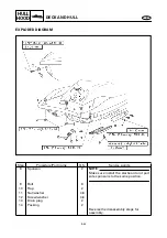
Page 222: ...al Engine unit Refer to ENGINE UNIT in chapter 5 Steering console cover assembly Refer to STEERING CONSOLE COVER 1 Band 2 2 Ventilation hose stern side 1 NOTE Route the ventilation hose bow side in fr...

Page 223: ...E HULL HOOD HOSES EXPLODED DIAGRAM Step Procedure Part name Q ty Service points 4 Band 1 5 Check valve 1 6 Oil tank breather hose 1 7 Fuel tank breather hose 2 Reverse the removal steps for installat...

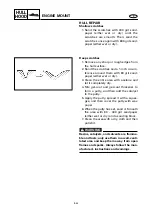
Page 224: ...end of check valve A and blow into it Air should come out from end B Connect the hose to the end of check valve B and blow into it Air should not come out from end A Ventilation hose installation 1 In...

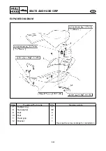
Page 225: ...D HAND GRIP EXPLODED DIAGRAM REMOVAL AND INSTALLATION CHART Step Procedure Part name Q ty Service points SEATS AND HAND GRIP REMOVAL Follow the left Step for removal 1 Seat assembly 1 2 Bolt 2 3 Seat...

Page 226: ...HOOD SEATS AND HAND GRIP EXPLODED DIAGRAM Step Procedure Part name Q ty Service points 7 Rubber ring 1 8 Nut washer 2 2 9 Bolt 2 10 Bolt 2 11 Hand grip 1 12 Bracket 1 Reverse the removal steps for in...

Page 227: ...8 35 E HULL HOOD SEATS AND HAND GRIP SERVICE POINTS Seat lock inspection 1 Inspect Seat lock Damage wear Replace...

Page 228: ...Step Procedure Part name Q ty Service points BATTERY BOX REMOVAL Follow the left Step for removal 1 Band 1 2 Fire extinguisher container 1 3 Band 1 4 Bolt 1 5 Battery negative lead 1 6 Bolt 1 7 Batter...

Page 229: ...vice points 12 Holder 1 13 Cap nut washer 2 2 14 Nut washer 4 4 15 Electrical box 1 16 Battery box 1 NOTE Before installing the battery box route the battery leads and battery breather hose through th...

Page 230: ...STEM REMOVAL Follow the left Step for removal Exhaust chamber assembly Refer to EXHAUST CHAMBER ASSEMBLY in chapter 5 1 Floatation 1 2 Hose clamp 1 3 Exhaust joint 1 4 Hose clamp 2 5 Rubber hose 1 6 W...

Page 231: ...points 9 Hose clamp 2 NOTE Remove parts 9 to 12 as a set 10 Water tank 1 11 Rubber hose 1 12 Exhaust outlet 1 13 Floatation 1 Reverse the removal steps for installation 4 Nm 0 4 m kgf 2 9 ft Ib 6 30...

Page 232: ...e Exhaust component parts sub assembly 1 Install Exhaust outlet Rubber hose Water tank NOTE Insert the exhaust outlet 45 mm 1 8 in a into the rubber hose Make sure that there is a surface distance of...

Page 233: ...HULL EXPLODED DIAGRAM REMOVAL AND INSTALLATION CHART Step Procedure Part name Q ty Service points DECK AND HULL DISASSEMBLY Follow the left Step for disassembly 1 Bolt 2 2 Bow eye 1 3 Nut 2 4 Rope ho...

Page 234: ...edure Part name Q ty Service points 8 Sponson 2 NOTE Make sure install the starboard and port side sponsons to the same position 9 Bolt 8 10 Flap 2 11 Nut washer 4 4 12 Screw washer 4 4 13 Drain plug...

Page 235: ...CHART Step Procedure Part name Q ty Service points ENGINE MOUNT REMOVAL Follow the left Step for removal Engine assembly Refer to ENGINE UNIT in chapter 5 1 Bolt 4 2 Damper 1 1 3 Damper 2 1 4 Bolt 8...

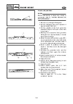
Page 236: ...n the entire area with acetone and let it completely dry 4 Mix gel coat and gel coat thickener to form a putty and then add the catalyst to the putty 5 Apply the putty spread it with a squee gee and t...

Page 237: ...1 or an equivalent primer onto both sides of the damaged area and then allow it to cure for approximately 30 minutes 6 Cover a piece of cardboard with wax paper 1 and then cover the damaged area with...

Page 238: ...62733 09 Nut Stainless steel M6 Material Pilot hole diameter FRP or SMC 9 1 9 2 mm 0 36 in Brass 9 4 mm 0 37 in Example 1 NOTE Before attempting to install the insert nut refer to WATER VEHICLE FRP R...

Page 239: ...rt nut and lock the bolt with the nut 3 as shown 9 Screw in the insert nut so that the top is flush with the FRP surface 10 Loosen the locknut and remove the bolt CAUTION Only use a steel bolt with a...

Page 240: ...h isopropyl alcohol to remove any residual adhesive Graphic installation 1 Mix 1 tablespoon of liquid detergent and water in a 1 quart spray bottle 2 Remove the backing from the new graphic 3 Spray th...

Page 241: ...E 9 TRBL ANLS CHAPTER 9 TROUBLE ANALYSIS TROUBLE ANALYSIS 9 1 TROUBLE ANALYSIS CHART 9 1...

Page 242: ...tors TROUBLE ANALYSIS CHART Problems Items to be checked ENGINE WILL NOT START ROUGH IDLING ENGINE STALLS ENGINE WILL NOT STOP POOR PERFORMANCE OVERHEATING LOOSE STEERING BILGE INCREASE IRREGULAR WARN...

Page 243: ...coil 7 Ignition coil 7 Rectifier regulator 7 Electrical sender s 7 Starter relay starter motor 7 YPVS unit 7 Battery 3 Fuse s 7 Wire harness electrical coupler s 7 HULL AND HOOD Steering column 8 Wate...

Page 244: ...Printed on recycled paper Printed in USA Feb 2000 1 CR F0X 28197 ZA 11 GP1200AY YAMAHA MOTOR CO LTD...

Page 245: ...O B Y O O B O B Y B Y B O B O B O W O B B W B O 1 2 3 B B B W B W B B B B B B B B W B Y B B B Br R R R R R R B R W R L R R Y Br Gy B Gy B R Br B W B W Br Br R R R W R W R W Br Br R R R L R Y R W R R...

Reviews: