PERIODIC MAINTENANCE AND MINOR REPAIR
6-36
6
3. If the electrolyte is at or below the
minimum level mark, continue with
the following steps.
4. Remove the rider seat. (See
page 3-9 for rider seat removal
and installation procedures.)
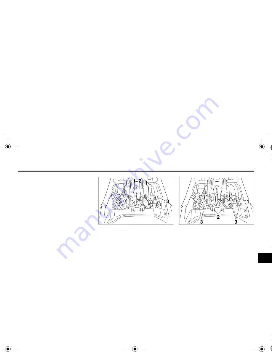
5. Disconnect the negative battery
lead from the battery.
6. Disconnect the positive battery
lead and the starter motor lead
from the starter motor relay.
7. Disconnect the couplers shown.
8. Remove the ignition coil assem-
blies by removing the bolts.
9. Add distilled water to raise the
electrolyte to the maximum level
mark.
1. Starter moter lead (black)
2. Positive battery lead (red)
3. Negative battery lead
1. Ignition coil assembly (
×
2)
2. Bolt (
×
2)
3. Coupler (
×
4)
E_5GK.book Page 36 Friday, May 31, 2002 10:59 AM
Summary of Contents for VMAX VMX12R
Page 1: ...5GK 28199 13 LIT 11626 16 20 VMX12R VMX12RC OWNER S MANUAL ...
Page 2: ...EAU03438 ...
Page 100: ...E_5GK book Page 49 Friday May 31 2002 10 59 AM ...
Page 107: ...SPECIFICATIONS 8 Specifications 8 1 E_5GK book Page 1 Friday May 31 2002 10 59 AM ...
Page 120: ...CONSUMER INFORMATION 9 8 9 E_5GK book Page 8 Friday May 31 2002 10 59 AM ...
Page 122: ...CONSUMER INFORMATION 9 10 9 E_5GK book Page 10 Friday May 31 2002 10 59 AM ...
Page 125: ...PRINTED IN JAPAN 2002 05 0 9 1 CR E PRINTED ON RECYCLED PAPER YAMAHA MOTOR CO LTD ...


